Independent SHAREhub process-safety awareness using fictional cases and a Great Britain baseline; check the applicable Northern Ireland duties and actual site arrangements. This course does not award a NEBOSH qualification, establish specialist competence or authorise hazardous work.
This reader supplies the complete teaching. Use the interactive LMS course for assessed activities, saved progress and completion.
LESSON 1
Start with fuel configuration and the initiating release
Start with fuel configuration and the initiating release.
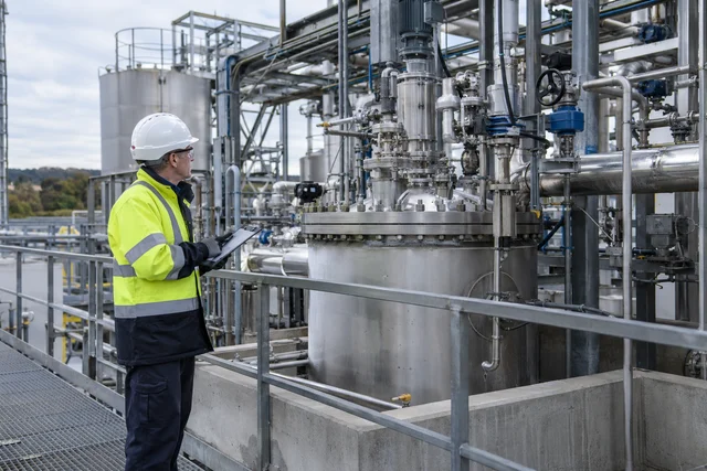
Existing SHAREhub photographic illustration. The written fictional case supplies the condition and decision evidence.
Understand the mechanism and the decision
A process-fire assessment begins with the substance, its condition and how it could be released. A liquid pool, a dispersed cloud and a pressurised jet present different fuel configurations. The ignition opportunity and the people or equipment exposed also vary.
The fire triangle supports understanding, but a triangle alone does not establish the plant scenario or the control design. Describe the release path, credible failures and consequences, then identify prevention and mitigation with their owners and verification.
Verify the control in the actual task
Use actual material and process information and keep engineered calculations and operating responses within the responsible competent system.
How do fuel, ignition and heat create different fire events?
A liquid leak is not itself a vapour-cloud explosion: it needs sufficient flammable vapour mixed with air, ignition, and conditions that allow rapid pressure development.
Flash point describes the test temperature at which a liquid gives off enough vapour for momentary ignition; it is not an ignition temperature or a safe-use temperature. Autoignition concerns ignition without a separate spark or flame under defined conditions. Flammable limits describe an ignitable gas or vapour mixture in air; do not apply a vapour LEL/UEL number to a dust cloud. Vapour density and ventilation affect where a release may travel. Use product-specific safety data and competent testing, not a generic number.
Heat moves by conduction through materials, convection with hot gases and radiation across space. In a process area, radiation from a pool or jet fire can heat nearby vessels, while hot smoke can defeat a protected route and combustion products can cause toxic exposure. Ask whether detection and isolation act before the assumed escalation; do not invent a safe exposure time.
Combustible dust has its own cloud ignition and pressure problem. An initial event in a collector can disturb layers of settled dust and create a larger secondary explosion. Dust identity, particle size, moisture, confinement and actual process conditions need specialist assessment; there is no universal safe dust layer or vent size.
A review uses the same short fire-triangle statement for a solvent pool and a pressurised gas leak.
Test the assumption
Only a larger triangle graphic. This does not establish acceptance. Shared combustion principles do not make the release mechanisms or controls identical.
Evidence before acceptance
Use actual material and process information and keep engineered calculations and operating responses within the responsible competent system.
Test your decision
What must be added to make the control review useful?
The actual release configurations, credible consequences and scenario-specific barriers.
Only a larger triangle graphic.
A statement that all fires require the same response.
Compare the explanation
The actual release configurations, credible consequences and scenario-specific barriers.
Shared combustion principles do not make the release mechanisms or controls identical.
Existing SHAREhub 2D teaching schematic. Use alongside the explanation and fictional case in this lesson.
Understand the mechanism and the decision
Avoiding unnecessary hazardous inventory or preventing release acts before the event develops. Detection, isolation, containment and fire protection have other defined roles along the scenario pathway. Their effectiveness depends on when they act and what they can achieve.
A proposed control should be linked to a specific failure or consequence. Equipment quantity is not a measure of independence or coverage. A system that limits escalation cannot automatically replace a missing measure needed to prevent the initiating release.
Verify the control in the actual task
Trace the event from source to people exposed and check what each proposed barrier is intended to do.
Which scenario and barrier details must an engineer establish?
Specify the actual substance and physical state, temperature, pressure, release and ignition scenarios before crediting detection, isolation, ventilation, drainage or explosion protection.
For a solvent transfer, obtain the safety data sheet, transfer inventory, hose and coupling design, overfill route, likely vapour path, ignition sources and occupied positions. A vapour detector only helps if placement, alarm response, final isolation element and safe state are designed and tested for that release; the emergency plan must protect people if isolation fails.
For a flour mill, obtain material test data and dust extraction design, then inspect deposits, likely primary ignition, connected duct paths and collector siting. Explosion venting, suppression or isolation needs a competent design based on the actual equipment and a safe discharge direction; a generic housekeeping procedure cannot replace it.
Distinguish combustion pressure from other explosion mechanisms
Distinguish combustion pressure from other explosion mechanisms.
Existing SHAREhub photographic illustration. The written fictional case supplies the condition and decision evidence.
Understand the mechanism and the decision
Rapid combustion can generate pressure as well as flame. Confinement, congestion and the release environment can affect pressure development and exposure. Explosion hazards can also involve physical expansion or vessel failure; the word explosion does not identify one universal mechanism.
A useful assessment identifies the material, energy source and sequence. Treating every event as a simple open fire can miss blast and debris. Equally, assuming every flammable release produces a severe explosion can obscure the conditions that must actually be assessed.
Verify the control in the actual task
Retain uncertainty until the competent investigation and scenario assessment establish the facts, rather than selecting controls from a dramatic description alone.
What does explosion and explosive combustion mean in workplace safety?
It means understanding how rapid burning can create blast, flame, fireball, missiles or escalation and then preventing the conditions that allow it.
Ordinary combustion is the chemical reaction we recognise as burning. Explosive combustion is rapid enough to produce pressure effects. In workplace terms, this can involve flammable gases, vapours, mists, combustible dusts, unstable materials, aerosols, oxygen enrichment or pressurised liquefied gases. See HSE ATEX and explosive atmospheres.
The topic should not be treated as theory only. A garage storing petrol, a joinery shop producing wood dust, a bakery handling flour, a fuel depot, a paint shop, a construction site using LPG, a chemical plant, a battery charging area and a fireworks retailer all need different levels of control.
The competent question is: what combustible material can be released or dispersed, how could it mix with air, what could ignite it, how confined or congested is the area, who could be harmed and what evidence proves controls are working?
Explosion terms in plain English - Explosion terms in plain English
Term
Meaning
Example
Explosive atmosphere
A mixture of air and dangerous substance where combustion can spread after ignition.
Petrol vapour in a poorly ventilated store.
Deflagration
A subsonic flame front that can still create damaging pressure.
Combustible dust ignited inside ductwork.
Detonation
A supersonic reaction front with very high pressure effects.
High-energy explosive event under particular conditions.
Vapour cloud explosion
Ignition of a dispersed flammable vapour cloud.
Fuel release forms a cloud and ignites.
Dust explosion
Ignition of dispersed combustible dust.
Flour or wood dust cloud ignites in extraction system.
BLEVE
Violent rupture of a vessel containing pressurised liquefied material.
Heated LPG cylinder ruptures and fireball forms.
Applied case
An incident description says only that a vessel exploded, with no account of contents or event sequence.
Test the assumption
That every explosion must have been the same kind of combustion. This does not establish acceptance. The label is not the mechanism; the sequence and conditions matter.
Evidence before acceptance
Retain uncertainty until the competent investigation and scenario assessment establish the facts, rather than selecting controls from a dramatic description alone.
Test your decision
What should the investigation and review establish?
That visible flame is the only consequence worth considering.
The actual energy, release and pressure-generation mechanism and relevant consequences.
That every explosion must have been the same kind of combustion.
Compare the explanation
The actual energy, release and pressure-generation mechanism and relevant consequences.
The label is not the mechanism; the sequence and conditions matter.
Include confinement and propagation in the scenario
Include confinement and propagation in the scenario.
Photorealistic illustrative UK workplace scene. Review checks: Avoid / redesign: Remove an unnecessary dust-generating stage or select a process that avoids combustible powder handling where feasible. Control the task: Securely isolate the collector and connected equipment; control stored energy and prevent access to hazardous dust-release zones. Verify before release: If the hazardous step remains, keep it within the task assessment and select the stronger feasible remaining controls.
Understand the mechanism and the decision
A combustible cloud or dust in a connected system can produce consequences beyond its first location. Geometry, confinement and routes of propagation affect the potential event. A source described as small does not by itself establish a small consequence.
Controls must address the relevant scenario and interfaces. An open doorway or outdoor location is not a universal guarantee against pressure effects, and a generic enclosure description is not a consequence calculation. Specialist assessment is needed where design decisions depend on those effects.
Verify the control in the actual task
Ask which interfaces and occupied locations the assessment covers and what evidence supports the selected protection, without inventing a safe pressure or separation.
What fire science explains explosion risk?
Explosion risk is explained by fuel, oxidant, ignition, mixture, confinement, dispersion and reaction speed.
A flammable gas or vapour usually needs to be within its flammable range. Too little fuel may be too lean to burn; too much fuel may be too rich until it mixes with more air. Dust behaves differently because particle size, moisture, turbulence, concentration and dispersion all influence explosibility.
Ignition sources can include flames, welding, grinding, hot surfaces, electrical sparks, static discharge, friction, impact, self-heating, chemical reaction, lightning or unsuitable equipment. Oxygen enrichment can make materials ignite more easily and burn more violently.
Usually air, but oxygen enrichment increases severity.
Prevent oxygen enrichment and leaks.
Mixture
Fuel concentration must be in a flammable or explosible range.
Ventilation, containment and release prevention.
Ignition
A source of enough energy starts combustion.
Ignition-source control and suitable equipment.
Dispersion
Dusts and vapours become more hazardous when dispersed.
Housekeeping, LEV and process enclosure.
Confinement
Pressure can build in rooms, vessels or ducts.
Relief, venting and layout design.
Congestion
Obstructions increase turbulence and flame acceleration.
Layout, separation and plant design.
Applied case
A proposed review stops at a vessel and ignores connected ducting and nearby congested equipment.
Test the assumption
Only the vessel label. This does not establish acceptance. The surrounding arrangement and connected routes can matter to escalation.
Evidence before acceptance
Ask which interfaces and occupied locations the assessment covers and what evidence supports the selected protection, without inventing a safe pressure or separation.
Test your decision
What should be included?
The relevant confinement, congestion and propagation pathways in the assessed scenario.
Only the vessel label.
An assumption that nearby open space removes every consequence.
Compare the explanation
The relevant confinement, congestion and propagation pathways in the assessed scenario.
The surrounding arrangement and connected routes can matter to escalation.
Existing SHAREhub photographic illustration. The written fictional case supplies the condition and decision evidence.
Understand the mechanism and the decision
Flammability limits describe a concentration range for a specified material and test or operating conditions. They are not universal numbers for every mixture, temperature or atmosphere. Vapour limits are also not interchangeable with dust explosibility measures.
A concentration outside a stated range at one point does not establish that every part of a changing cloud is outside it. Mixing and dilution can create different conditions elsewhere or later. Gas monitoring must have an appropriate purpose, location, method and response within the site system.
Verify the control in the actual task
Use the approved assessment and monitoring arrangements; this course does not set alarm values, gas-free criteria or universal concentration limits.
How should LEL and UEL be understood?
LEL/LFL is the lower flammable concentration and UEL/UFL the upper concentration under defined test conditions. A concentration below a detector alarm or above the UEL at one point does not establish a safe area: mixing, dilution and sensor location can create flammable pockets.
The lower explosive limit is often the first number people remember, but it should not be used in isolation. A detector reading below LEL does not automatically prove the whole area is safe, because concentration can vary across a cloud and a detector only measures where it is located. Equally, a mixture above the upper limit can become flammable as it mixes with fresh air.
Gas detection alarms are commonly set as a percentage of LEL, so workers must understand what the alarm means. A low alarm may require stopping work, withdrawal or trained investigation from a safe location under the verified response plan; it does not authorise entry into a suspected cloud. A high alarm may mean immediate evacuation or emergency shutdown. The exact response should be defined in the site's procedures.
MeaningToo little fuel in air to propagate flame at that point.
Control implicationDo not assume the whole area is safe; cloud concentration can vary.
ConditionFrom LEL through UEL under stated test conditions
MeaningThe mixture is within its flammable range under those conditions.
Control implicationStop work, control ignition, investigate, isolate and follow alarm response.
ConditionBetween LEL and UEL
MeaningThe mixture can ignite and flame can propagate.
Control implicationPrevent ignition and remove people from the affected area.
ConditionAbove UEL
MeaningToo much fuel and too little oxygen at that point.
Control implicationDilution can bring the cloud back through the flammable range, so treat as dangerous.
ConditionPercentage of LEL
MeaningDetector alarm scale showing how close the measured concentration is to the LEL.
Control implicationAlarm setpoints must be understood, maintained and linked to action.
ConditionLocal pockets
MeaningDifferent parts of the cloud may have different concentrations.
Control implicationDetector placement, ventilation and area control matter.
The published limits depend on test conditions and can shift with gas mixture, oxygen concentration, temperature and pressure. Use validated substance/process data; do not transfer one table value to an oxygen-enriched, heated or mixed atmosphere without competent analysis.
Specific official context: HSE HSG140. HSG140 2015 Great Britain safe use/handling, transfer, ignition and contaminated-rag control context; container and bulk storage are separate HSG51/HSG176 routes; historic law/standards require current checking. Substance/mixture conditions and detailed combustion predictions require validated data and specialist review.
Applied case
A single result above a quoted upper limit is offered as proof the whole release area cannot burn.
Test the assumption
Every part of the release is permanently safe. This does not establish acceptance. A local result and a condition-specific range cannot establish the entire evolving atmosphere.
Evidence before acceptance
Use the approved assessment and monitoring arrangements; this course does not set alarm values, gas-free criteria or universal concentration limits.
Test your decision
What is the correct interpretation?
Every part of the release is permanently safe.
The same vapour figure can be used for any combustible dust.
The actual material, measurement scope and changing cloud conditions still need assessment.
Compare the explanation
The actual material, measurement scope and changing cloud conditions still need assessment.
A local result and a condition-specific range cannot establish the entire evolving atmosphere.
Connect dispersion with the actual release environment
Connect dispersion with the actual release environment.
Photorealistic illustrative UK workplace scene. Review checks: Avoid / redesign: Avoid the transfer until storage capacity and safe receiving route are proven. Control the task: Use independent high-level protection, closed transfer, containment and isolation. Verify before release: Capacity or route uncertain: do not start.
Understand the mechanism and the decision
Cloud behaviour depends on the material and release conditions as well as the surrounding environment. Ventilation, weather, low points, drainage and congestion can influence where material travels or accumulates. The absence of visible vapour does not establish that no hazardous concentration exists.
Use the actual credible release and site information, not a generic rule about vapour density or wind. A workplace observation can identify a concern, but it cannot replace a competent dispersion assessment where one is needed. Odour is not a reliable test of atmosphere safety.
Verify the control in the actual task
Identify the relevant locations and barriers and obtain the responsible assessment of changed ventilation, layout or operating conditions.
How do vapour clouds move and disperse?
Cloud movement depends on density, weather, ventilation, obstacles, drains, terrain and how long the release continues.
A cloud is not a neat circle on a drawing. Heavier-than-air vapour can slump, hug the ground and move into low points. Wind can carry vapour downwind. Still conditions or poor ventilation can allow accumulation. Indoors, ventilation patterns, open doors, process ventilation and building geometry can all change cloud movement.
This is why emergency plans should not rely only on the leak source. The plan should consider where the cloud could travel, who might be exposed, which ignition sources need controlling and when evacuation or sheltering decisions are needed.
Factors affecting vapour cloud movement
Factor
Effect
Practical management point
FactorVapour density
EffectHeavier vapours may collect at low level; lighter gases may rise or disperse differently.
Practical management pointPlace detectors and ventilation based on gas behaviour, not convenience.
FactorWind and weather
EffectWind can dilute or transport vapour; still conditions can allow build-up.
Practical management pointConsider weather in emergency response and major accident modelling.
FactorVentilation
EffectGood ventilation can dilute vapour; poor ventilation can allow accumulation.
Practical management pointVerify ventilation performance and maintain extract systems.
FactorRelease duration
EffectLonger releases create larger clouds and more exposure to ignition sources.
Practical management pointUse detection, isolation and shutdown to reduce duration.
FactorTerrain and drainage
EffectBunds, trenches, sumps and drains can channel vapour or liquid.
Practical management pointControl drains, low points and spill pathways.
FactorObstacles
EffectPlant, pipework and structures can affect turbulence and mixing.
Practical management pointConsider layout and congestion in hazard studies.
Sources and references
Specific official context: HSE DSEAR in detail. HSE GB supports dangerous-substance risk principles; HSENI-approved L138 supplies separate NI context only where cited. Examples require competent task assessment and field evidence; engineering design, alarm values and named legal/technical approval remain held.
Applied case
A drain route and low-level enclosure are omitted because no visible cloud is present during a walk-round.
Test the assumption
Only whether anyone can see vapour now. This does not establish acceptance. Observation at one time does not establish how a future release disperses.
Evidence before acceptance
Identify the relevant locations and barriers and obtain the responsible assessment of changed ventilation, layout or operating conditions.
Test your decision
What must the review address?
Only whether the area smells normal.
The credible release and accumulation pathways under relevant conditions.
Only whether anyone can see vapour now.
Compare the explanation
The credible release and accumulation pathways under relevant conditions.
Observation at one time does not establish how a future release disperses.
Explain delayed ignition of a dispersed flammable cloud
Explain delayed ignition of a dispersed flammable cloud.
Existing SHAREhub photographic illustration. The written fictional case supplies the condition and decision evidence.
Understand the mechanism and the decision
A release can disperse and mix with air before ignition occurs. A flammable cloud may produce a flash fire or, where conditions support significant pressure generation, a vapour-cloud explosion. A release does not automatically become either a fire or an explosion.
The assessed pathway must connect loss of containment, dispersion, ignition opportunities and consequences. Preventing the release and controlling relevant ignition sources remain distinct functions. Detection does not itself prevent a leak; it needs an effective response within the specified system.
Verify the control in the actual task
Check the containment controls, detector purpose and response, and the actual evidence that those functions remain available.
What makes a release more severe?
Release size and duration, material properties, weather, drainage, congestion, enclosure, ignition timing and exposed people alter the possible cloud and consequences.
A vapour may enter drains, culverts or buildings, and a cloud can outgrow the classified zone drawn for normal operation. Lower and upper explosive limits describe a laboratory flammable range for a specific material and conditions; they are not an evacuation threshold or permission to work. Blast and occupied-building vulnerability require competent, site-specific study. HSE RR1190 illustrates enclosure and turbulence effects but is research, not a universal blast calculation.
A detector is proposed as proof that a hose failure cannot release flammable material.
Test the assumption
A detector always makes containment unnecessary. This does not establish acceptance. Different barriers act at different points in the scenario pathway.
Evidence before acceptance
Check the containment controls, detector purpose and response, and the actual evidence that those functions remain available.
Test your decision
What is wrong with this claim?
Detection and its response do not by themselves prevent the initiating hose failure.
A detector always makes containment unnecessary.
A detector reading predicts every future consequence.
Compare the explanation
Detection and its response do not by themselves prevent the initiating hose failure.
Different barriers act at different points in the scenario pathway.
Do not use a zone drawing as a consequence boundary
Do not use a zone drawing as a consequence boundary.
Photorealistic illustrative UK workplace scene. Review checks: Avoid / redesign: Remove an unnecessary solvent use or open decanting step through process redesign. Control the task: Use an assessed dedicated dispensing area separated from ignition sources, occupied routes and incompatible materials. Verify before release: Confirm receiving capacity, line-up, connection condition and the required protective functions before transfer; stop on a fault.
Understand the mechanism and the decision
Hazardous-area information supports equipment and ignition-control arrangements within its basis. It is not a map of the full effects of every major release. A cloud, fire, pressure effect or debris hazard can involve a different footprint from a normal classification boundary.
Layout and occupied-location decisions need the relevant scenario assessment. A person should not choose a safe muster location or a temporary cabin position solely from a zone line. Refer changed occupancy or layout through the responsible planning and emergency systems.
Verify the control in the actual task
Use the current layout, credible scenarios and emergency arrangements; do not create a generic exclusion distance from the course.
Which activities and outcomes does this guide cover?
Use it for credible flammable gas, vapour and mist release scenarios in storage, transfer, process, maintenance and abnormal operation.
Examples include petrol loading, liquefied petroleum gas (LPG) systems, solvent handling, vapour recovery, start-up, line breaking and contractor hot work. It does not replace a site Dangerous Substances and Explosive Atmospheres Regulations (DSEAR) assessment, hazardous-area classification, quantitative consequence study, manufacturer instructions or emergency plan. Dust explosions, boiling liquid expanding vapour explosion (BLEVE), pressure-only rupture and toxic clouds have different mechanisms, although they may coexist and need separate assessment. Control of Major Accident Hazards (COMAH) adds duties only if a site falls within its threshold and tier rules.
A temporary occupied cabin is proposed just beyond a normal zone boundary without a consequence review.
Test the assumption
Accept the zone boundary as a universal safe-distance line. This does not establish acceptance. Classification and consequence assessment have different purposes.
Evidence before acceptance
Use the current layout, credible scenarios and emergency arrangements; do not create a generic exclusion distance from the course.
Test your decision
What is required?
Accept the zone boundary as a universal safe-distance line.
Place the cabin wherever it is convenient for access.
Review the actual release, fire/explosion and occupancy scenarios through competent planning.
Compare the explanation
Review the actual release, fire/explosion and occupancy scenarios through competent planning.
Classification and consequence assessment have different purposes.
Existing SHAREhub photographic illustration. The written fictional case supplies the condition and decision evidence.
Understand the mechanism and the decision
A jet fire follows ignition of a continuing pressurised release. A pool fire involves burning material collected as a liquid pool. The release mechanism affects direction, spread and escalation. Both can cause severe thermal exposure, but their source-control and protective requirements must fit the actual scenario.
The distinction supports planning; it does not authorise a worker to approach or extinguish a process fire. A visible flame shape alone cannot establish the source condition. Use the emergency arrangements and provide factual information from a safe position.
Verify the control in the actual task
Check which credible fire types the assessment and emergency plan cover and how source information reaches responsible responders.
How do jet fires and pool fires differ?
The difference matters because the controls, modelling assumptions, emergency response and escalation routes are not the same.
A jet fire is dominated by release pressure, hole size, phase, direction, flame length, momentum and isolation time. A pool fire is dominated by liquid release rate, drainage, bunding, pool size, surface area, fuel properties, ventilation and firewater management. Both can expose people and equipment to thermal radiation, but the geometry of the flame and the duration of exposure often differ.
For a process safety management (PSM) learner, this comparison is not academic. It shapes what should be inspected: pressure systems, emergency isolation valves and flange management for jet fires; bunds, drains, overfill prevention, transfer control and spill response for pool fires.
Pressurised gas, vapour or flashing liquid release.
Liquid release that collects on a surface.
Flame shape
Directional flame with high momentum.
Broader surface flame shaped by pool area.
Main escalation concern
Flame impingement on vessels, pipework, supports and cables.
Sustained thermal radiation to adjacent plant, structures and escape routes.
Key prevention controls
Mechanical integrity, pressure containment, isolation, leak detection and permit control.
Tank integrity, transfer control, overfill prevention, bunds, drains and spill control.
Mitigation controls
Fire/gas detection, emergency shutdown, depressurisation, deluge or passive fire protection.
Fuel-compatible, engineered extinguishing systems; separately, exposure cooling where assessed; firewater containment and separation.
Weak evidence
No credible release cases, no isolation timing or no impingement review.
No pool size assumptions, no drainage plan or no firewater/run-off plan.
Extinguishment, fire control and exposure cooling are different duties. The substance, application method and competent response design determine suitable media; water is not interchangeable with a compatible extinguishing system for petrol or other low-flash-point liquids. This comparison does not prescribe a firefighting technique. Read HSE fire-protection guidance.
Applied case
A generic briefing assumes every process fire is a shallow liquid spill.
Test the assumption
Only rename the briefing. This does not establish acceptance. The fuel configuration and continuing source change the scenario.
Evidence before acceptance
Check which credible fire types the assessment and emergency plan cover and how source information reaches responsible responders.
Test your decision
What should be corrected?
Treat all flame shapes as evidence of the same release.
Include relevant pressurised-release and pooled-liquid scenarios with their different barriers.
Only rename the briefing.
Compare the explanation
Include relevant pressurised-release and pooled-liquid scenarios with their different barriers.
The fuel configuration and continuing source change the scenario.
Trace drainage and thermal escalation beyond the first pool
Trace drainage and thermal escalation beyond the first pool.
Photorealistic illustrative UK workplace scene. Review checks: Avoid / redesign: At design or modification stage, remove a pressurised LPG transfer or redundant dead leg where the duty can be met without it; remove the connected inventory before intrusive work under an approved isolation plan. Control the task: Use compatible pipework and mechanical integrity controls; keep vulnerable people and plant outside the predicted flame and radiation footprint. Verify before release: Hold or stop for unverified isolation, residual pressure or impaired protection.
Understand the mechanism and the decision
A released liquid can spread along surfaces or drainage routes and form a fire away from its original source. Thermal effects can harm people and challenge neighbouring equipment. The visible edge of a pool is not a general safe exposure boundary.
Containment and drainage arrangements should be assessed together with layout and emergency access. Opening a drain to remove a pool may transfer the hazard elsewhere. Changes in a route or nearby occupancy need the responsible review rather than a local convenience decision.
Verify the control in the actual task
Verify the intended drainage state and accepted layout through the actual site arrangements; do not operate drains as an improvised emergency response.
How do drainage and containment affect pool fire risk?
Pool fire size is often controlled by where liquid can travel and how quickly it is contained.
A small leak on paper can become a large fire if liquid spreads across a concrete yard, enters an open drain, flows to a low point or bypasses bunding. Drainage design, bund integrity, kerbs, isolation valves, interceptors, sumps and firewater routes can therefore be major accident barriers. HSE HSG176 (GB) covers flammable-liquid storage, containment and drainage.
Managers should challenge whether drains are normally open, whether people know how to isolate them, whether bund valves are left open, whether firewater can be retained, and whether emergency teams understand the environmental consequences of firefighting water.
Control
Good practice question
Failure scenario
Bunds
Is capacity, condition and valve position checked?
Bund valve left open during tank leak. (see HSE HSG176)
Drain isolation
Can drains be closed quickly and safely?
Burning liquid travels to interceptor or public drain. (see HSE HSG176)
Surface grading
Does the yard slope towards safe containment?
Fuel flows under vehicles or towards building. (see HSE HSG176)
Spill response
Are kits, foam, absorbents and competent responders available?
Secondary fuel load increases fire growth. (see HSE HSG176)
Applied case
A proposed temporary drain path carries a potential flammable spill towards another occupied area.
Test the assumption
Only whether the source area looks cleaner. This does not establish acceptance. Moving a hazard is not the same as controlling its consequences.
Evidence before acceptance
Verify the intended drainage state and accepted layout through the actual site arrangements; do not operate drains as an improvised emergency response.
Test your decision
What is the relevant review question?
Whether the changed release and fire pathway is acceptably controlled for people and equipment.
Only whether the source area looks cleaner.
Only whether the liquid leaves the first work position.
Compare the explanation
Whether the changed release and fire pathway is acceptably controlled for people and equipment.
Moving a hazard is not the same as controlling its consequences.
Existing SHAREhub photographic illustration. The written fictional case supplies the condition and decision evidence.
Understand the mechanism and the decision
A BLEVE involves sudden vessel failure and rapid expansion of liquid held above its atmospheric boiling point. The physical event can produce pressure effects and fragments. If the released material is flammable, ignition can add a fireball and severe thermal consequences.
The mechanism is not limited to combustion, and a BLEVE does not always include a fireball. External fire can challenge vessel strength as well as affect internal pressure. Awareness should lead to recognition and planned protective action, not a close approach to judge vessel condition.
Verify the control in the actual task
Use the actual vessel, contents and credible exposure conditions in the competent scenario and emergency review.
A BLEVE is a physical rupture mechanism
A boiling liquid expanding vapour explosion involves sudden failure of a vessel containing liquid above its atmospheric boiling temperature. Rapid flashing and expansion can create severe blast and fragments.
Fictional learning example
Separate the evidence from the decision
Part of the picture
What the example establishes
Physical mechanism
A pressurised liquid can flash rapidly when containment fails.
Additional consequence
If the material is flammable and ignites, fire effects may also occur.
Boundary
A relief device alone does not establish that a fire-heated vessel cannot fail.
Pause and decide: Must every BLEVE include a flammable vapour-cloud explosion?
Compare the reasoning
No. Keep the physical rupture/expansion mechanism separate from any subsequent combustion. The material, condition and scenario determine additional consequences. Use the established emergency plan and exclusion arrangements; this awareness example does not authorise an approach or firefighting intervention.
What is a BLEVE?
A BLEVE is the sudden failure of a vessel containing liquid above its atmospheric boiling point, followed by rapid vapour expansion.
BLEVE stands for boiling liquid expanding vapour explosion. In simple terms, a pressurised liquid is suddenly released from containment, flashes into vapour and expands violently. Where the liquid is flammable, the release may ignite and form a large fireball with severe thermal radiation.
The classic example is a pressure vessel or LPG sphere exposed to external fire. The fire heats the vessel wall and the contents. Pressure may rise, relief valves may lift, and the wetted wall may initially be cooled by the liquid inside. As liquid level falls or fire impingement continues, part of the wall may become unwetted, overheat and lose strength. Sudden rupture can then release the inventory almost instantly.
A BLEVE should therefore be treated as a major accident hazard involving pressure, fire, fragments, thermal radiation, emergency response and escalation to neighbouring plant.
Pressurised liquid. Liquid is held above atmospheric pressure. Failure releases stored energy.
Flashing. Liquid rapidly changes to vapour. Expansion can be explosive.
Vessel failure. The containment ruptures or tears. Fragments may travel significant distances.
Fireball. Flammable contents ignite after release. Thermal radiation can be fatal or escalate plant.
Escalation. Nearby vessels, pipework or buildings are affected. One event can become a major accident.
Applied case
A briefing says a vessel containing a non-flammable pressurised hot liquid cannot create a BLEVE hazard.
Test the assumption
BLEVE means only a flammable fireball. This does not establish acceptance. Flammability affects additional consequences; it is not the sole physical basis of a BLEVE.
Evidence before acceptance
Use the actual vessel, contents and credible exposure conditions in the competent scenario and emergency review.
Test your decision
What is the correction?
BLEVE means only a flammable fireball.
Non-flammable contents remove every pressure and fragment hazard.
The physical vessel-failure and rapid-expansion hazard still needs assessment.
Compare the explanation
The physical vessel-failure and rapid-expansion hazard still needs assessment.
Flammability affects additional consequences; it is not the sole physical basis of a BLEVE.
Understand why relief alone does not settle vessel-heating risk
Understand why relief alone does not settle vessel-heating risk.
Photorealistic illustrative UK workplace scene. Review checks: Avoid / redesign: Avoid large pressurised LPG inventory where feasible Control the task: Separate fire exposure, protect vessel, maintain relief and emergency isolation Verify before release: Major-hazard owner verifies separation/relief and fire response; evacuate on escalating fire exposure See HSE bulk LPG valves and pressure relief
Understand the mechanism and the decision
A pressure relief device has a defined duty. It cannot guarantee vessel integrity when fire weakens the wall or other limitations defeat its protective purpose. Discharge and escalation hazards also need assessment. A fitted device is therefore not a complete vessel-fire safety case.
Planning may involve inventory, layout, integrity, fire protection, isolation and emergency strategy as an integrated system. These need competent design and assurance. An awareness course cannot state a universal safe approach distance or time before failure; a reassuring sound from a relief device is not proof of safety.
Verify the control in the actual task
Follow the actual emergency arrangements and provide information from safety. Re-entry and recovery need authorised assessment of the changed condition.
Why is a relief valve insufficient on its own?
A pressure relief valve may limit internal pressure rise from external heat, but it cannot guarantee vessel integrity when fire weakens the wall, exposure is severe, a discharge escalates fire or the device is impaired. The protection case must combine layout, inventory, fire prevention, isolation, vessel integrity, relief and cooling with a credible emergency strategy.
Do not assign a universal safe distance or time-to-failure from a generic page. Competent site analysis and emergency services must use actual vessel, contents, fire and terrain information.
Applied case
A heated vessel is declared safe to approach because its relief device is operating.
Test the assumption
Approach because pressure relief guarantees wall integrity. This does not establish acceptance. Relief operation does not establish that the vessel or its surroundings are safe.
Evidence before acceptance
Follow the actual emergency arrangements and provide information from safety. Re-entry and recovery need authorised assessment of the changed condition.
Test your decision
What is the defensible response?
Wait a fixed training-example time and then inspect it closely.
Use the planned emergency protection and competent assessment; do not treat relief operation as safe-approach evidence.
Approach because pressure relief guarantees wall integrity.
Compare the explanation
Use the planned emergency protection and competent assessment; do not treat relief operation as safe-approach evidence.
Relief operation does not establish that the vessel or its surroundings are safe.