SHARE Knowledge Hub
Explosion prevention, relief, isolation and suppression
Explosion protection begins by preventing dangerous fuel-air mixtures and ignition. Relief directs pressure along a designed path, isolation limits propagation through connected plant, and suppression acts quickly to reduce pressure rise. Each option has a defined design basis, performance limits, inspection needs and failure modes; none makes an uncontrolled release acceptable. Apply the correct GB or NI DSEAR duties and specialist engineering review.
Understanding Explosion prevention, relief, isolation and suppression
Typical hazard: Explosion protection is used instead of prevention | How harm occurs: Release, dust cloud or ignition source remains credible and frequent while relief/suppression is treated as the main control.
Why this matters at work
Explosion relief deliberately allows an initiated event to discharge so that the protected boundary avoids uncontrolled failure. The opening behaviour and effective flow must suit the event and the strength of the complete equipment. The assessment includes doors, panels, covers, access points, supports and connected ductwork. Ordinary process pressure relief for a slower overpressure cause cannot be assumed to perform the same rapid function.
Protective systems must be linked to a defined scenario. Combustible dust and flammable gas or vapour can ignite and develop thermal and pressure effects. Physical pressure failure or energetic reaction can follow different mechanisms; do not infer combustion or a suitable dust relief method from an explosion label. Consequence changes with material properties, concentration, ignition, enclosure, vessel strength, volume, geometry, congestion, venting path, connected plant, occupancy and the vulnerability of surrounding structures. In dust handling, a primary event can disperse deposited dust and create a destructive secondary explosion. In connected plant, flame and pressure may propagate from a filter, silo, dryer, mill or conveyor into multiple equipment items.
How organisations manage this in practice
Prevention should lead the protection strategy. Reducing combustible inventory and releases, controlling ignition and preventing hazardous concentrations can reduce both event likelihood and reliance on a device working on demand. Dust deposits also matter because an initial event can disturb them. Inerting has its own hazards and design conditions and must not be introduced as an informal operating adjustment.
Human performance is part of every engineered barrier. People identify an abnormal condition, interpret alarms, prevent ignition, maintain exclusion zones, follow permits, hand over impairment, inspect vents and decide whether plant can continue. Designs and procedures should support realistic action under time pressure, noise, lighting, shift change and competing production demands. Avoid relying on a single person to remember a rarely used action or to reach a hazardous area before an event develops. Use clear indications, accessible controls, simple alarm response, independent checking where risk justifies it, competent supervision and training based on actual scenarios.
Evidence should include DSEAR assessment, scenario/bow-tie record, material/dust/reactivity information, calculations and specialist design basis where relevant, drawings/P&IDs/zone plans, equipment certificates, installation/commissioning records, cause-and-effect charts, safe operating limits, inspection and proof-test records, calibration, maintenance/defect history, impairment register, permits, MOC, pre-startup reviews, training/competence, emergency drills, investigations and leadership review. Evidence must be controlled so that current plant and drawings agree.
Match each protection function to its design limits
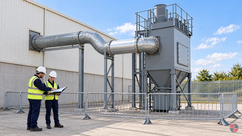
After a duct is lengthened or rerouted, the process engineer holds affected operation until the specialist confirms propagation, connected volumes, relief discharge and isolation or suppression performance for the changed configuration. A device certificate does not approve the whole modified system.
A changed duct requires evidence for the connected system
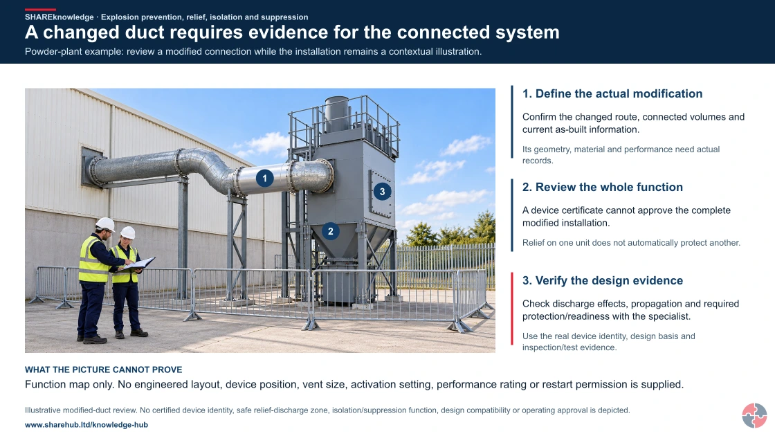
Full written explanation
Two colleagues stand outside a connected barrier beside a dust-collector form with a duct from the building, a brighter replacement spool, hopper/bin and an unlabelled bolted panel. Markers identify the changed spool, connected collector and panel form. A panel cannot be identified as a rated explosion vent from appearance. No installed isolation or suppression, discharge safety, design rating, test, live operating status or approved protection layout is established.
Powder-plant example: review a modified connection while the installation remains a contextual illustration.
- Define the actual modification. Confirm the changed route, connected volumes and current as-built information.
- Review the whole function. A device certificate cannot approve the complete modified installation.
- Verify the design evidence. Check discharge effects, propagation and required protection/readiness with the specialist.
Change the pathway
- A bright spool is only a cue. Its geometry, material and performance need actual records.
- Connection can carry consequences. Relief on one unit does not automatically protect another.
- A panel is not a verified vent. Use the real device identity, design basis and inspection/test evidence.
Evidence check: Function map only. No engineered layout, device position, vent size, activation setting, performance rating or restart permission is supplied.
Compatible design and current readiness govern the changed system
Primary references: HSE: explosion-relief principles — verify the current engineering basis · HSE: dust explosion hazards and connected plant
Open the complete HD image (new tab)Download image

Compatible design and current readiness govern the changed system
Primary references: HSE: explosion-relief principles — verify the current engineering basis · HSE: dust explosion hazards and connected plant
- Prevention — Reduce the likelihood of an explosive atmosphere or effective ignition; residual scenarios may remain.
- Relief or venting — Limit pressure within the design basis; the discharge must be safe and propagation addressed.
- Isolation — Limit propagation between connected equipment; it does not prevent every initiating explosion.
- Suppression — Detect and suppress within specified conditions; readiness and maintenance are essential.
Maintenance verifies installation and tests against the competent design basis; the technical owner records as-built details, limits, device readiness and hand-back. Keep the impaired-protection stop route active. The linked HSE technical material explains principles but contains older standards references; obtain current competent engineering validation and do not infer generic sizing rules.
Content amended 19 October 2026 by the SHARE Knowledge Hub editorial team. This records an editorial content change; the existing technical-review and approval status still applies.
Follow pressure and flame through connected plant
A flour silo, filter and duct can connect a local event to another vessel. Prevention, relief, isolation and suppression each have a different design purpose and evidence requirement.

Prevent the scenario
Assess material, release, deposits, dispersion and ignition sources for the actual system.
Limit escalation
Use the competent design basis for relief/discharge, propagation isolation and any detection/suppression; check their dependencies and exposed people.
Verify availability
Match inspection/test and maintenance evidence to the required function. Hold an impaired or unknown critical function through the authorised process.
No vent size, discharge distance, isolation location or suppression specification is implied.
What evidence proves explosion protection still works?
Name the explosion scenario, prevention and mitigation layers, design assumptions, owners, inspection and test results, impairments and hold points. An installed vent or suppression bottle is not proof that the connected system remains protected.
Best-practice guide: Explosion prevention, relief, isolation and suppression
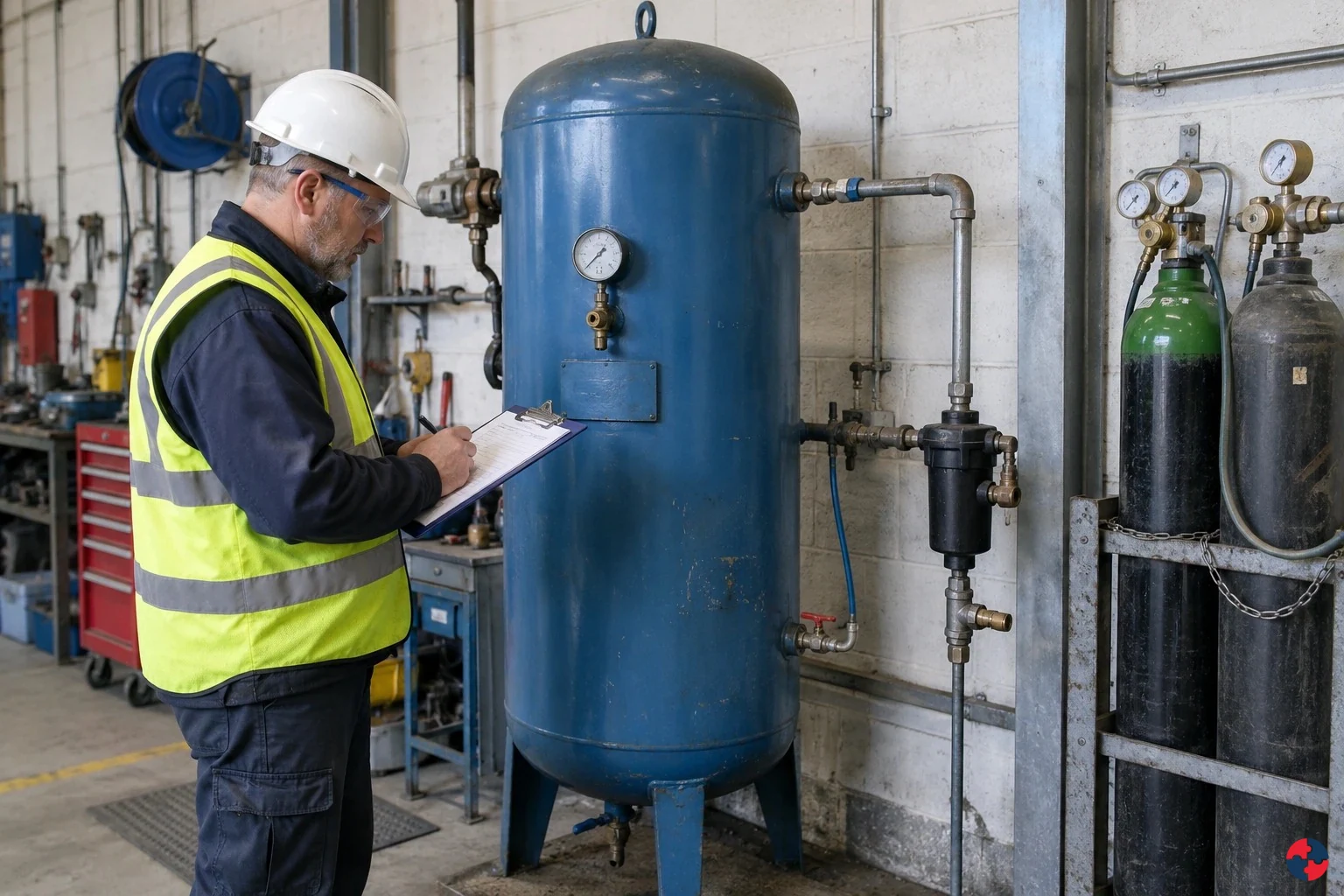
What evidence proves explosion protection still works?
Name the explosion scenario, prevention and mitigation layers, design assumptions, owners, inspection and test results, impairments and hold points. An installed vent or suppression bottle is not proof that the connected system remains protected. Explosion protection begins by preventing dangerous fuel-air mixtures and ignition.
Turn explosion prevention, relief, isolation and suppression knowledge into a decision
Explosion protection begins by preventing dangerous fuel-air mixtures and ignition. Relief directs pressure along a designed path, isolation limits propagation through connected plant, and suppression acts quickly to reduce pressure rise. Design assumptions, material data, drawings, commissioning tests, inspection records, impairment decisions and technical hand-back.
A decision that changes work
Monitor extraction, housekeeping and device health; prevent hot work and unapproved modifications that could defeat isolation or suppression. Verify installed configuration, tests, safe vent route, device readiness and operating limits before restart.
Warning signs and responses
Blocked relief panel: Explosion pressure cannot discharge as designed. Suppression fault alarm: System may not activate on demand. Dust layers returning quickly: Primary or secondary explosion fuel remains.
Choose controls for explosion prevention, relief, isolation and suppression
Prevention: Stop explosive atmosphere or ignition forming. Relief or venting: Release explosion pressure safely. Isolation: Stop flame and pressure propagation. Suppression: Detect and extinguish early explosion development. Explosion resistance: Allow equipment to withstand expected pressure. Read the full control table for qualifications, ownership and verification. Use the actual task and applicable jurisdiction; existing technical approval remains unchanged.
Use the full explosion prevention, relief, isolation and suppression lesson
Use the full topic for the decision points, practical examples, detailed control tables and source scope. HSE guidance applies to Great Britain; use HSENI for the Northern Ireland route and the source’s stated jurisdiction. A simplified guide does not change the page’s technical-review or approval status.

Read all six steps as text
1. What evidence proves explosion protection still works?
Name the explosion scenario, prevention and mitigation layers, design assumptions, owners, inspection and test results, impairments and hold points.
- Avoid / redesign: Stop explosive atmosphere or ignition forming.
- Control the task: Stop flame and pressure propagation.
- Verify before release: Closed transfer, ventilation, inerting and ignition control.
Name the explosion scenario, prevention and mitigation layers, design assumptions, owners, inspection and test results, impairments and hold points. An installed vent or suppression bottle is not proof that the connected system remains protected. Explosion protection begins by preventing dangerous fuel-air mixtures and ignition.
Apply it: Which part of this plan would you check at the workface before authorising the task?
2. Turn explosion prevention, relief, isolation and suppression knowledge into a decision
Use the evidence to improve the actual work arrangement.
- Change at source: Stop explosive atmosphere or ignition forming.
- Make it observable: Closed transfer, ventilation, inerting and ignition control.
- Keep useful evidence: Design assumptions, material data, drawings, commissioning tests, inspection records, impairment decisions and technical hand-back.
Explosion protection begins by preventing dangerous fuel-air mixtures and ignition. Relief directs pressure along a designed path, isolation limits propagation through connected plant, and suppression acts quickly to reduce pressure rise. Design assumptions, material data, drawings, commissioning tests, inspection records, impairment decisions and technical hand-back.
Apply it: What evidence would show that the change improves this task, rather than only completing a record?
3. A decision that changes work
Example: a practical application of the existing topic lesson.
- Setting: Flour silo, connected dust filter and transfer duct at a food-processing site.
- Act: Reduce dust release and ignition; confirm material test data, filter and silo volumes, vent discharge path, duct connections and protection design basis.
- Hold / review: Stop transfer if a critical collector fails, a vent is obstructed, isolation is impaired or changed ducting has not been reassessed.
Monitor extraction, housekeeping and device health; prevent hot work and unapproved modifications that could defeat isolation or suppression. Verify installed configuration, tests, safe vent route, device readiness and operating limits before restart.
Apply it: At which point would you hold this example, and what evidence would allow it to proceed?
4. Warning signs and responses
Connect the task, the route to the person and the control that can fail.
- Blocked relief panel: Explosion pressure cannot discharge as designed.
- Suppression fault alarm: System may not activate on demand.
- Dust layers returning quickly: Primary or secondary explosion fuel remains.
Blocked relief panel: Explosion pressure cannot discharge as designed. Suppression fault alarm: System may not activate on demand. Dust layers returning quickly: Primary or secondary explosion fuel remains.
Apply it: Who could be exposed, including other trades, cleaners, maintainers and people nearby?
5. Choose controls for explosion prevention, relief, isolation and suppression
Start with the stronger practicable options and verify their effect.
- Prevention: Stop explosive atmosphere or ignition forming.
- Relief or venting: Release explosion pressure safely.
- Isolation: Stop flame and pressure propagation.
- Suppression: Detect and extinguish early explosion development.
- Explosion resistance: Allow equipment to withstand expected pressure.
Prevention: Stop explosive atmosphere or ignition forming. Relief or venting: Release explosion pressure safely. Isolation: Stop flame and pressure propagation. Suppression: Detect and extinguish early explosion development. Explosion resistance: Allow equipment to withstand expected pressure. Read the full control table for qualifications, ownership and verification. Use the actual task and applicable jurisdiction; existing technical approval remains unchanged.
Apply it: Which stronger option can be used here, and who will verify it before accepting the remaining risk?
6. Use the full explosion prevention, relief, isolation and suppression lesson
Follow the official sources below and retain the task-specific evidence.
- Official guidance: HSE DSEAR in detail
- Official guidance: HSE explosion relief technical measures
- Task decision: Design assumptions, material data, drawings, commissioning tests, inspection records, impairment decisions and technical hand-back.
Use the full topic for the decision points, practical examples, detailed control tables and source scope. HSE guidance applies to Great Britain; use HSENI for the Northern Ireland route and the source’s stated jurisdiction. A simplified guide does not change the page’s technical-review or approval status.
Apply it: Which official source and full-topic section will you use to resolve the next decision?
DSEAR means Dangerous Substances and Explosive Atmospheres Regulations. Prevention comes first: eliminate or substitute dangerous materials where practicable, then use engineering containment, ventilation, inerting and ignition control; administrative permits and PPE only support residual risk. Relief, isolation, suppression and resistant construction are engineered mitigation, each with a defined failure limit.
| Barrier area | What good looks like | Evidence |
|---|---|---|
| Cause | Identify credible causes rather than vague hazards. | Scenario list. |
| Top event | Define the loss of control, release, ignition, explosion or failed decision point. | Bow-tie or fault tree. |
| Consequence | Describe escalation, harm, business impact and emergency interface. | Consequence analysis. |
| Prevention barriers | Controls that stop the top event occurring. | Barrier register and performance standards. |
| Mitigation barriers | Controls that limit consequences after the top event. | Proof tests, inspections and drill evidence. |
| Impairment controls | Bypasses, degraded safeguards and overdue tests are authorised and temporary controls set. | Impairment log. |
| ALARP record | Risk reduction decisions are documented and periodically reviewed. | ALARP decision record. |
A flour silo connects to a filter by duct. The plant reduces dust release and ignition first; a specialist checks vent path and isolation so a filter event cannot propagate to the silo. After a duct change, operations pauses transfer until the revised system basis, device tests and safe discharge area are verified.
Who needs to understand explosion prevention and protection?
This topic is essential for people who design, operate, maintain, inspect or manage equipment and processes where explosive atmospheres are credible.
Who needs to understand explosion prevention and protection? — part 1 of 3


Read the complete visual as text
- This topic is essential for people who design, operate,…: This topic is essential for people who design, operate, maintain, inspect or manage equipment and processes where explosive atmospheres are credible.
- Process engineers: Need to specify prevention and protection measures against credible release, dust and pressure scenarios.
- Maintenance teams: Need to inspect and maintain relief panels, isolation devices, suppression systems, sensors and hazardous area equipment.
Who needs to understand explosion prevention and protection? — part 2 of 3


Read the complete visual as text
- Operators and supervisors: Need to recognise barrier impairments, dust build-up, bypasses, blocked vents and unsafe operating conditions.
- DSEAR assessors: Need to decide where prevention is enough and where engineered mitigation is needed.
Who needs to understand explosion prevention and protection? — part 3 of 3


Read the complete visual as text
- Senior leaders: Need to understand that explosion protection is safety critical and needs resourcing, inspection and review.
- NEBOSH PSM and Fire learners: Need to explain prevention, relief, isolation, suppression, design limitations and assurance evidence in scenarios.
Process engineers
Need to specify prevention and protection measures against credible release, dust and pressure scenarios.
Maintenance teams
Need to inspect and maintain relief panels, isolation devices, suppression systems, sensors and hazardous area equipment.
Operators and supervisors
Need to recognise barrier impairments, dust build-up, bypasses, blocked vents and unsafe operating conditions.
DSEAR assessors
Need to decide where prevention is enough and where engineered mitigation is needed.
Senior leaders
Need to understand that explosion protection is safety critical and needs resourcing, inspection and review.
NEBOSH PSM and Fire learners
Need to explain prevention, relief, isolation, suppression, design limitations and assurance evidence in scenarios.
How can I practise this topic in 3D?

Dust demonstrator: a relief panel is mistaken for propagation isolation
All related inspection points 1 across 1 location
Crown Fuels terminal 1 inspection point
Practice in the SHAREhub environment. Browser practice is separate from workplace competence and formal learning records.
What are the key facts about explosion prevention, relief, isolation and suppression?
The key facts are that prevention is strongest, engineered mitigation must be correctly designed, and protection systems must be maintained as safety critical barriers.
What are the key facts about explosion prevention, relief, isolation and suppression? — part 1 of 3


Read the complete visual as text
- The key facts are that prevention is strongest, engineered…: The key facts are that prevention is strongest, engineered mitigation must be correctly designed, and protection systems must be maintained as safety critical barriers.
- Prevention comes first: Avoiding explosive atmospheres is more reliable than managing an explosion after it starts.
- Relief needs a safe path: Vents and relief panels must discharge to a safe place and must not be blocked by storage or later modifications.
What are the key facts about explosion prevention, relief, isolation and suppression? — part 2 of 3


Read the complete visual as text
- Isolation prevents propagation: An explosion can travel through ducts, pipes or conveyors unless isolation is designed into the system.
- Suppression is time critical: Detection and suppressant discharge must happen early enough to control pressure rise.
What are the key facts about explosion prevention, relief, isolation and suppression? — part 3 of 3


Read the complete visual as text
- Design basis must stay current: Dust properties, materials, layout, ducting, strength and operating conditions can invalidate protection assumptions.
- Inspection proves health: A relief panel, isolation valve or suppression bottle is not a barrier unless it is installed correctly and proven ready.
Prevention comes first
Avoiding explosive atmospheres is more reliable than managing an explosion after it starts.
Relief needs a safe path
Vents and relief panels must discharge to a safe place and must not be blocked by storage or later modifications.
Isolation prevents propagation
An explosion can travel through ducts, pipes or conveyors unless isolation is designed into the system.
Suppression is time critical
Detection and suppressant discharge must happen early enough to control pressure rise.
Design basis must stay current
Dust properties, materials, layout, ducting, strength and operating conditions can invalidate protection assumptions.
Inspection proves health
A relief panel, isolation valve or suppression bottle is not a barrier unless it is installed correctly and proven ready.
What do prevention, relief, isolation and suppression mean?
They are the main control families used to stop explosions occurring or reduce the harm if prevention fails.
Prevention controls the conditions needed for an explosion: fuel, oxidant, ignition, dispersion, confinement and process upset. Examples include substitution, closed handling, ventilation, inerting, dust control, leak prevention, hazardous area equipment, static control and hot-work permits. See HSE DSEAR in detail.
Relief and venting are mitigation controls. They do not stop ignition, but they aim to prevent equipment or structures being destroyed by pressure. Isolation prevents an explosion in one vessel or duct from propagating into connected plant. Suppression detects rapid pressure rise or flame and injects suppressant quickly enough to limit the event.
These controls are often interdependent. A dust collector may need housekeeping to prevent external dust layers, explosion relief to protect the collector, isolation to protect upstream equipment and maintenance to prove the system is ready.
| Control family | Purpose | Example |
|---|---|---|
| Prevention | Stop explosive atmosphere or ignition forming. | Closed transfer, ventilation, inerting and ignition control. |
| Relief or venting | Release explosion pressure safely. | Explosion relief panel on dust collector. |
| Isolation | Stop flame and pressure propagation. | Fast-acting valve or chemical isolation on ducting. |
| Suppression | Detect and extinguish early explosion development. | Pressure detector and suppressant bottle system. |
| Explosion resistance | Allow equipment to withstand expected pressure. | Vessel designed for defined explosion pressure. |
| Emergency response | Protect people if control layers fail. | Evacuation, isolation and incident command. |
How should explosive atmospheres be prevented?
Explosive atmospheres should be prevented by controlling releases, dust clouds, vapours, ventilation, oxygen, process conditions and ignition sources.
The first design question should be whether the dangerous substance or process condition can be eliminated or reduced. If not, the system should prevent release and accumulation. This may mean closed transfer, sealed equipment, local exhaust ventilation, inerting, temperature control, cleaning standards, leak detection and operating limits. See HSE DSEAR in detail.
Ignition control is only one part of prevention. A workplace should also prevent the flammable mixture forming. For combustible dust, that means preventing dust escape, build-up and dispersion. For flammable vapour, it means containment, ventilation and controls on decanting, transfer and drainage.
| Prevention area | Control examples | Evidence |
|---|---|---|
| Substitution | Less flammable or less dusty material. | Substitution review and procurement record. |
| Inventory reduction | Minimum quantities in use and storage. | Inventory limits and stock checks. |
| Containment | Closed systems, sealed ducts, maintained pipework. | Inspection and leak-test records. |
| Ventilation | Dilution or local exhaust to prevent accumulation. | Ventilation checks and LEV records. |
| Inerting | Reduced oxygen where technically appropriate. | Oxygen monitoring and design records. |
| Ignition control | ATEX equipment, bonding, grounding and hot-work controls. | Inspection and permit evidence. |
| Housekeeping | Dust layer standards and cleaning. | Cleaning schedule and inspections. |
How does explosion relief or venting work?
Explosion relief provides a designed weak path for pressure to escape before equipment or structures fail catastrophically.
Explosion relief is common on dust collectors, silos, bins, vessels and some enclosures. The relief area, panel type, opening pressure, ducting and discharge direction must suit the material, vessel strength, expected pressure rise and the place where flame, pressure and debris may go. See HSE explosion relief technical measures.
Relief can introduce new hazards. A vent may protect equipment but discharge flame into a walkway, building, roof space or neighbouring plant if poorly located. Relief devices can also be defeated by corrosion, paint, blocked vents, added ducting, snow, storage or unauthorised modifications.
| Check | Why it matters | Evidence |
|---|---|---|
| Design basis | Vent size depends on material and equipment strength. | Design file and dust test data. |
| Discharge direction | Flame and pressure must go to a safe place. | Layout review and exclusion zones. |
| Obstruction | Blocked vents may not open or discharge safely. | Inspection photos and housekeeping checks. |
| Condition | Corrosion, paint or damage can impair function. | Inspection and maintenance records. |
| Ducting changes | Added ducting can alter performance. | MOC record and specialist review. |
| People nearby | Relief may harm people outside the equipment. | Occupancy review and signage. |
Why is explosion isolation needed?
Explosion isolation is needed to stop flame, pressure or burning material travelling through connected equipment.
Many dust and vapour systems are connected by ducts, pipework, conveyors or transfer lines. An explosion in one item of equipment can propagate into upstream or downstream equipment unless isolation is provided. See HSE preventing dust explosions.
Isolation can be mechanical, chemical or process-based depending on the system. Examples include fast-acting valves, flap valves, rotary valves, chemical isolation, flame arresters and process separation. The key issue is that the selected device must be suitable for the material, pressure, duct, direction of propagation and maintenance regime.
| Isolation method | Typical use | Key limitation |
|---|---|---|
| Fast-acting valve | Duct or pipe isolation after detection. | Needs correct detection and response time. |
| Flap valve | Dust extraction systems where flow direction suits. | Must be installed correctly and maintained. |
| Rotary valve | Powder transfer isolation where suitable. | Clearance, strength and material suitability matter. |
| Chemical isolation | Suppression agent stops propagation in duct. | Needs specialist design and maintained suppressant. |
| Flame arrester | Prevents flame transmission in some vapour systems. | Needs correct application and cleaning. |
| Physical separation | Layout reduces propagation and escalation. | Requires space and design discipline. |
How does explosion suppression work?
Explosion suppression detects early explosion development and rapidly discharges suppressant to limit pressure rise.
Suppression systems are highly time-sensitive. Sensors detect pressure rise or flame, a control unit triggers discharge and suppressant is released into the protected volume. The design must match the protected equipment, material properties, volume, pressure development and process conditions.
Suppression is not a fit-and-forget control. Bottles, actuators, detectors, control panels, wiring, nozzles and isolation interlocks must be inspected, maintained and managed under change control. A disabled suppression system should be treated as a safety critical impairment.
| Component | What to check | Evidence |
|---|---|---|
| Detector | Correct location, condition and calibration. | Inspection and test records. |
| Control panel | Power, alarms, fault status and logic. | Panel test and alarm review. |
| Suppressant container | Pressure, charge, expiry and condition. | Service certificate. |
| Discharge path | Nozzles clear and correctly oriented. | Inspection and maintenance record. |
| Interlocks | Shutdown or isolation actions occur as designed. | Cause-and-effect test. |
| Impairment rule | Operations know what to do if unavailable. | Impairment permit and compensating measures. |
When is explosion-resistant equipment relevant?
Explosion-resistant equipment is relevant where equipment is designed to withstand defined explosion pressure without losing containment.
Explosion-resistant design can be useful, but only within a defined design basis. It does not mean the equipment is indestructible. The design depends on expected pressure, material behaviour, vessel volume, strength, connected systems and relief or isolation arrangements.
If process conditions change, if a different powder is introduced, if ducting is modified or if the equipment is corroded, the original design assumptions may no longer be valid. This is why MOC and inspection are essential.
| Question | Why it matters | Evidence |
|---|---|---|
| What pressure is it designed for? | Protection only applies within design limits. | Design certificate and calculations. |
| What material was assumed? | Dust or vapour properties influence pressure. | Material test data and SDS. |
| What has changed? | Process changes can invalidate protection. | MOC and technical review. |
| What condition is it in? | Corrosion or damage reduces strength. | Inspection and repair records. |
| What is connected? | Connected ducts may propagate explosion. | Isolation and layout review. |
| Who owns it? | Safety critical equipment needs accountability. | Asset register and owner. |
What are the design limitations of explosion protection?
Design limitations are the assumptions that define when a protection system will and will not work.
A protection system is only as good as its assumptions. Dust particle size, moisture, explosibility, pressure rise, vessel volume, duct length, vent ducting, equipment strength, flow direction, maintenance condition and occupancy all affect whether the selected protection will work. See HSE explosion relief technical measures.
HSE explosion-relief and HSG103 material explains mechanisms and common design questions, but some referenced standards and COMAH-era wording are dated. A competent specialist must use current product, test and design standards for the actual dust or gas, protected volume, duct, vent path and occupancy. These pages supply no vent area, Kst or Pmax design calculation.
Teams should record the design basis in plain operational language. Operators and managers do not need every calculation, but they do need to know which changes trigger review: new material, new throughput, modified ducting, changed fan, different cleaning regime, blocked vent route or altered operating temperature.
| Assumption | What can invalidate it | Control |
|---|---|---|
| Material properties | Different powder, moisture or particle size. | Material change review and testing. |
| Vent path | Storage, ducting or building change blocks discharge. | Inspection and MOC. |
| Vessel strength | Corrosion, damage or unapproved repair. | Inspection and repair control. |
| Detection time | Sensor location or process change delays detection. | Functional testing and specialist review. |
| Isolation direction | Flow reversal or modified duct changes propagation. | Design review. |
| Occupancy | People moved into vent discharge zone. | Layout and people-at-risk review. |
Illustrative seven-step decision route; this is a SHARE teaching example, not a prescribed legal checklist.
| Step | Action | Check | Failure mode | Hold point |
|---|---|---|---|---|
| Avoid | Reduce combustible inventory or remove unnecessary open handling. | Design lead checks alternate process risk. | A substitute may create another hazard. | No substitution without reassessment. |
| Prevent atmosphere | Contain releases and control dust or vapour concentration. | Operations verifies enclosure and extraction. | A failed collector recreates the cloud. | Stop transfer on critical loss. |
| Control ignition | Match equipment and hot-work rules to actual hazardous zones. | Competent assessor checks site condition. | Product mark alone does not prove suitability. | No ignition-capable work in uncontrolled zone. |
| Choose protection | Specialist compares venting, isolation, suppression and resistant design. | Check Kst/Pmax or gas data, geometry and connected plant as applicable. | A vent may expose people or ducts may propagate flame. | Hold design without credible basis. |
| Verify installation | Confirm direction, protected volume and device interfaces. | Commissioning tests as-built connections. | A bypass or obstruction defeats function. | No start with unresolved defect. |
| Manage impairment | Track tests, maintenance, bypasses and changes. | Owner reviews test evidence and duration. | A stale design file conceals drift. | Stop or reduce operation on barrier loss. |
| Review | Reassess material, throughput, layout and incident learning. | Technical authority signs revised basis. | Old sizing may not fit new dust. | No restart before changed basis is approved. |
How should dust extraction and powder handling systems be protected?
Dust systems should be protected by preventing dust escape, controlling ignition, maintaining extraction and using relief, isolation or suppression where needed.
Dust extraction and powder systems can create both process risk and building risk. A leak, blocked filter, failed housekeeping regime or modified duct can allow dust to accumulate. The primary explosion may start inside equipment, but the worst harm may occur when settled dust becomes airborne in a secondary explosion.
Protection should be chosen from the actual system: collectors, silos, mills, dryers, conveyors, filters, elevators, hoppers and ducts may each need different controls. A competent assessment should identify where ignition could occur and how an event could propagate.
| System part | Risk | Control |
|---|---|---|
| Dust collector | Explosion inside filter housing. | Relief, isolation and maintenance. |
| Ductwork | Explosion propagation. | Isolation and cleaning access. |
| Silo or bin | Dust cloud ignition during filling or discharge. | Venting, grounding and ignition control. |
| Conveyor | Flame propagation and hot bearing ignition. | Bearing monitoring and isolation. |
| Milling or grinding | Heat, sparks and fine dust generation. | Temperature, tramp metal and process controls. |
| Workroom surfaces | Secondary explosion fuel. | Housekeeping and dust-layer inspections. |
How should flammable vapour and gas systems be protected?
Flammable vapour and gas systems should prevent releases, avoid accumulation, control ignition and provide emergency isolation where needed.
For vapour systems, prevention often focuses on containment, ventilation, hazardous area classification, suitable equipment, drainage control, transfer procedures, gas detection, pressure relief and emergency shutdown. Hot work and intrusive maintenance require particular discipline because residues can remain in tanks, drums and pipework.
Relief, flame arresters or explosion-resistant design may be relevant in some systems, but they must be selected by competent specialists and maintained. A flame arrester that is fouled, incorrectly installed or used outside its design basis can create false reassurance.
| Control | Application | Evidence |
|---|---|---|
| Containment integrity | Tanks, hoses, flanges, seals and pipework. | Inspection and leak records. |
| Ventilation | Indoor or enclosed transfer areas. | Design and test records. |
| Gas detection | Areas where release may accumulate. | Calibration and alarm response. |
| Emergency isolation | Stop feed to release or fire. | Functional tests and drill evidence. |
| Flame arresters | Suitable vapour systems where flame propagation is credible. | Inspection, cleaning and design basis. |
| Hot-work control | Tanks, drums and plant with residues. | Cleaning, testing, isolation and permit records. |
How should explosion protection systems be inspected and maintained?
Explosion protection systems should be managed as safety critical barriers with defined inspection, testing, maintenance and impairment rules.
A protection system can fail silently. A relief panel may be painted shut, a suppression bottle may lose pressure, a detector may be dirty, an isolation valve may stick, a vent duct may be blocked or a bypass may be left in place after maintenance.
Maintenance should be planned from the design basis. The asset register should identify each protection system, owner, inspection frequency, test method, spares, competence requirement, defect priority and what to do if the system is unavailable.
| Barrier | Inspection question | Impairment response |
|---|---|---|
| Relief panel | Is it intact, unobstructed, correctly fitted and corrosion-free? | Stop or restrict operation if relief cannot function. |
| Isolation device | Does it close or activate as designed? | Apply compensating measures and technical review. |
| Suppression system | Are detectors, bottles, panels and nozzles healthy? | Treat fault as safety critical impairment. |
| Hazardous area equipment | Is equipment suitable and undamaged? | Repair, replace or isolate. |
| Ventilation or LEV | Is airflow effective and dust/vapour controlled? | Stop high-risk task until control restored. |
| Housekeeping | Are dust layers within standard? | Clean safely and fix dust escape source. |
How should management of change protect explosion controls?
Management of change should trigger review whenever materials, process conditions, equipment, layout or occupancy could affect explosion protection.
Many explosion protection failures begin as small changes: a different powder, increased throughput, new ductwork, a moved workstation, stored pallets in front of a vent, a changed cleaning method or a replacement fan. Each may affect the assumptions behind the original design.
The MOC screen should ask whether the change affects dangerous substances, dust generation, vapour release, ventilation, hazardous areas, ignition sources, relief paths, isolation devices, suppression systems, emergency access or people at risk.
| Change | Why it matters | Review needed |
|---|---|---|
| New material | Explosibility, moisture or particle size may differ. | Material data and protection design. |
| Increased throughput | More dust or vapour may be generated. | Ventilation and relief capacity. |
| Duct modification | Propagation and vent performance may change. | Isolation and pressure review. |
| Equipment replacement | ATEX suitability or strength may differ. | Specification and installation check. |
| Layout change | Vent discharge or access may be affected. | Occupied area and relief path review. |
| Maintenance bypass | Protection may be temporarily unavailable. | Impairment control and authorisation. |
How should emergency plans reflect explosion protection?
Emergency plans should recognise what the protection systems can and cannot do, and what people must do if they are impaired or fail.
Explosion relief, isolation and suppression are not permission to keep people near a hazard. Emergency arrangements should identify warning signs, evacuation routes, isolation points, emergency shutdown, firefighting limits, exclusion zones, firewater runoff and communication with emergency services.
Drills should test realistic scenarios: suppression fault during operation, dust build-up discovered, flammable vapour alarm, blocked explosion relief, hot work on contaminated equipment or fire exposure to pressure vessels.
| Scenario | Emergency concern | Planning output |
|---|---|---|
| Suppression fault | Protected plant may no longer be safe to operate. | Impairment procedure and shutdown rule. |
| Explosion relief activation | Flame and debris may discharge. | Exclusion zone and response plan. |
| Dust explosion | Secondary explosion risk remains. | Evacuation and re-entry control. |
| Vapour release | Ignition may occur away from release point. | Gas detection and evacuation boundary. |
| Fire near vessels | BLEVE or escalation risk. | Cooling strategy and withdrawal criteria. |
| Firewater runoff | Environmental harm from contaminated water. | Drain isolation and runoff control. |
Which major accidents show why explosion protection matters?
Buncefield and combustible dust events show that prevention, separation, protection and barrier assurance must all work together.
Buncefield demonstrates the need to prevent releases and control escalation before relying on emergency response. A fuel overfill developed into a large vapour cloud and explosion. Explosion protection thinking asks whether overfill prevention, independent trips, containment, vapour dispersion assumptions, ignition control and emergency planning were credible and assured.
Combustible dust events across industry repeatedly show the same pattern: dust escape, poor housekeeping, ignition, primary explosion and secondary explosion. Relief and isolation may reduce consequences, but prevention, cleaning, maintenance and management of change are usually just as important.
| Scenario | Protection lesson | Audit question |
|---|---|---|
| Fuel vapour cloud explosion | Prevention and ignition control are stronger than response after release. | Are release scenarios controlled and tested through DSEAR and process safety review? |
| Dust collector explosion | Relief may protect the collector but isolation is needed to prevent propagation. | Are relief and isolation devices installed, inspected and unobstructed? |
| Secondary dust explosion | Housekeeping is an explosion-control barrier. | Are dust layers measured and acted on, not just cleaned occasionally? |
| Hot work on tanks or drums | Residues can create explosive atmospheres even when vessels look empty. | Are cleaning, gas testing and permits robust before hot work starts? |
What legal duties apply to explosion prevention and protection?
Apply the current GB or NI dangerous-substance rules to the actual process. COMAH adds major-accident duties only for qualifying inventories; relief, isolation or suppression design needs a competent technical basis, not just a regulation name.
| Where | Instrument or rule | Practical boundary |
|---|---|---|
| Great Britain | Dangerous Substances and Explosive Atmospheres Regulations 2002 | GB dangerous-substance fire and explosion risk duties. |
| Northern Ireland | Dangerous Substances and Explosive Atmospheres Regulations (Northern Ireland) 2003 | NI dangerous-substance fire and explosion risk duties. |
| Great Britain | Control of Major Accident Hazards Regulations 2015 | GB major-accident prevention and mitigation duties for qualifying establishments. |
| Northern Ireland | Control of Major Accident Hazards Regulations (Northern Ireland) 2015 | NI major-accident duties, MAPP, SMS, safety reports and tier boundaries. |
| Great Britain | Health and Safety at Work etc. Act 1974 | GB general work-safety duties |
| Northern Ireland | Health and Safety at Work (Northern Ireland) Order 1978 | NI general work-safety duties |
| Great Britain | Management of Health and Safety at Work Regulations 1999 | GB risk assessment and prevention arrangements |
| Northern Ireland | Management of Health and Safety at Work Regulations (Northern Ireland) 2000 | NI risk assessment and prevention arrangements |
GB DSEAR 2002 and NI DSEAR 2003 are separate instruments. Verify the inventory and threshold before applying COMAH 2015. A site without COMAH status can still have a serious dust or vapour explosion risk under DSEAR.
How should explosion protection appear in a risk register?
The risk register should link each explosion scenario to prevention barriers, mitigation barriers, owners, design assumptions and inspection evidence.
A useful risk register entry does not simply say 'explosion protection fitted'. It states what scenario the device protects against, the design basis, what conditions would invalidate it, who maintains it and what happens if it is impaired.
For example, a dust collector with relief panels and isolation should record the dust tested, equipment volume, relief route, isolation type, inspection frequency, fault response and MOC triggers.
| Field | What to record | Example |
|---|---|---|
| Scenario | The protected explosion event. | Dust explosion in collector. |
| Prevention barriers | Controls that prevent atmosphere or ignition. | LEV, grounding, cleaning and hot-work control. |
| Mitigation barriers | Relief, isolation, suppression or resistant design. | Relief panel and flap valve. |
| Design basis | Material and operating assumptions. | Wood dust properties and collector volume. |
| Owner | Person or function accountable. | Engineering manager. |
| Inspection | Inspection and test requirement. | Monthly visual checks and annual specialist service. |
| Impairment rule | What happens if barrier is unavailable. | Stop dust process until protection restored. |
How could Crownway Fuels Ltd manage explosion protection?

Crownway Fuels Ltd could manage explosion protection by treating each device and control as a safety critical barrier linked to a named scenario.
A decision that changes work — part 1 of 3


Read the complete visual as text
- 1. Task and setting: Flour silo, connected dust filter and transfer duct at a food-processing site.
- 2. People and prerequisites: Operators, process engineer, specialist protection designer, maintenance lead and supervisor; dust properties and as-built drawings are available.
- 3. Before the task: Reduce dust release and ignition; confirm material test data, filter and silo volumes, vent discharge path, duct connections and protection design basis.
A decision that changes work — part 2 of 3


Read the complete visual as text
- 1. Check during work: Monitor extraction, housekeeping and device health; prevent hot work and unapproved modifications that could defeat isolation or suppression.
- 2. Stop, hold or refer: Stop transfer if a critical collector fails, a vent is obstructed, isolation is impaired or changed ducting has not been reassessed.
A decision that changes work — part 3 of 3


Read the complete visual as text
- 1. Completion and hand-back: Verify installed configuration, tests, safe vent route, device readiness and operating limits before restart.
- 2. Retained evidence: Design assumptions, material data, drawings, commissioning tests, inspection records, impairment decisions and technical hand-back.
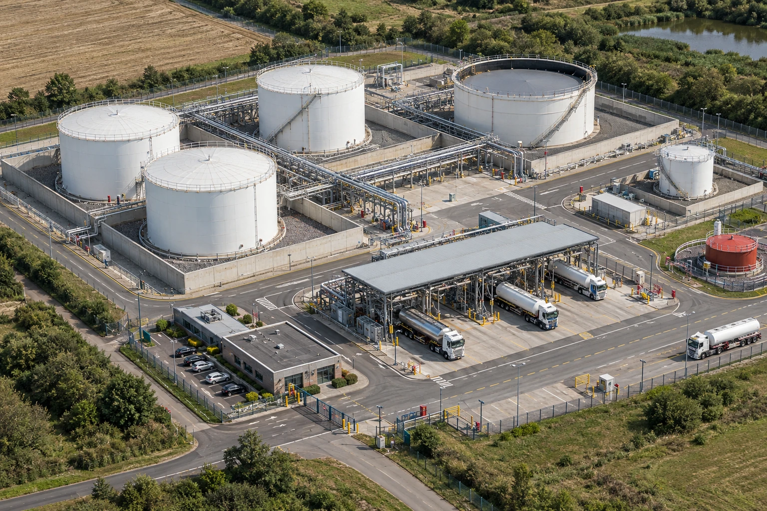
Crownway Fuels Ltd (worked example). a fuel storage and distribution business with bulk flammable liquids, tanker loading, hazardous areas, vapour control, contractors, hot work and emergency arrangements.
Crownway would begin with prevention. It would reduce release potential through tank integrity, overfill prevention, closed transfer, compatible hoses, inspection, procedures and operator training. It would reduce ignition through hazardous area classification, suitable electrical equipment, bonding and grounding, hot-work control, vehicle rules and contractor induction.
Where mitigation is required, Crownway would define exactly what each system is for. Flame arresters, pressure relief, emergency isolation, gas detection, shutdown logic or explosion-resistant equipment would be listed in a safety critical asset register with design basis, owner, inspection frequency and impairment rules.
The site would audit not just the paperwork but the physical condition: vents clear, devices accessible, bonding clamps used, permit isolations verified, contractors controlled, MOC completed after any equipment change and emergency drills testing credible vapour release or fire escalation scenarios.
| Management activity | How Crownway would apply it | Evidence produced |
|---|---|---|
| Assess and analyse | Identify vapour release, tank, transfer, hot work and escalation scenarios. | DSEAR assessment and barrier register. |
| Implement prevention | Use containment, overfill prevention, ventilation, bonding and ignition control. | Inspection records and permit evidence. |
| Implement mitigation | Define relief, flame arresters, gas detection, shutdown and emergency isolation where needed. | Safety critical asset register. |
| Train and authorise | Train operators, maintainers and contractors on protection limits and impairment rules. | Competence matrix and authorisations. |
| Maintain and inspect | Inspect and test protection systems, hazardous area equipment and emergency isolation. | Maintenance records and defect close-out. |
| Manage change | Review protection basis after material, equipment, layout or process change. | MOC and pre-start-up review. |
| Learn and improve | Review leaks, alarms, permit findings, Buncefield learning and emergency exercises. | Leadership review and action tracker. |
A decision that changes work
Task, material and setting: Flour silo, connected dust filter and transfer duct at a food-processing site.
People and prerequisites: Operators, process engineer, specialist protection designer, maintenance lead and supervisor; dust properties and as-built drawings are available.
Before: Reduce dust release and ignition; confirm material test data, filter and silo volumes, vent discharge path, duct connections and protection design basis.
During: Monitor extraction, housekeeping and device health; prevent hot work and unapproved modifications that could defeat isolation or suppression.
Hold or stop: Stop transfer if a critical collector fails, a vent is obstructed, isolation is impaired or changed ducting has not been reassessed.
Completion and hand back: Verify installed configuration, tests, safe vent route, device readiness and operating limits before restart.
Evidence: Design assumptions, material data, drawings, commissioning tests, inspection records, impairment decisions and technical hand-back.
Which petroleum controls illustrate explosion prevention and isolation?
Use only the relevant fuel containment, ignition and transfer-control concepts. These petroleum scenes do not demonstrate dust suppression or establish an engineered explosion-protection design.
Different protection functions answer different questions
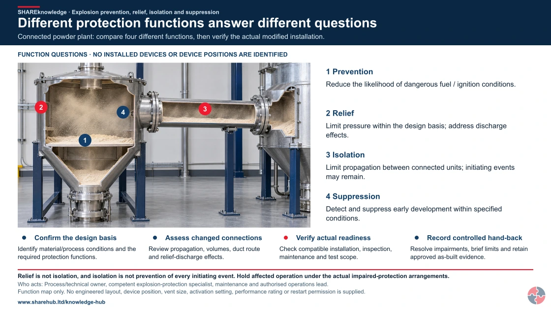
Full written explanation
The exact inspected realistic HD powder-enclosure cutaway is meaningfully reused because it makes the enclosed fuel conditions, pressure boundary and continuous connection between two volumes visible. Four native 1/2/3/4 FUNCTION questions distinguish prevention that reduces fuel/ignition likelihood, relief that limits pressure within its design basis and creates discharge effects, isolation that limits propagation between connected units, and suppression that detects and suppresses early development within specified conditions. Markers identify questions about these physical regions, not installed devices or device positions: no vent panel, explosion isolator, detector or suppressant system is identified or verified in the picture. Relief on one unit cannot be treated as protection for all connected plant, and none of the functions replaces prevention of every initiating event. The complete original four checks below connect design basis, changed volumes/duct/discharge, actual compatible installation/readiness/test evidence, and controlled impairment resolution/as-built hand-back. No activation setting, vent size, pressure rating, engineered layout, component compatibility, discharge zone, operating limit or restart permission is supplied. The existing modified-duct exterior HD pathway, all native controls and its private/source/output assets remain exactly unchanged.
Connected powder plant: compare four different functions, then verify the actual modified installation.
- Confirm the design basis. Identify material/process conditions and the required protection functions.
- Assess changed connections. Review propagation, volumes, duct route and relief-discharge effects.
- Verify actual readiness. Check compatible installation, inspection, maintenance and test scope.
- Record controlled hand-back. Resolve impairments, brief limits and retain approved as-built evidence.
When the evidence does not fit: Relief is not isolation, and isolation is not prevention of every initiating event. Hold affected operation under the actual impaired-protection arrangements.
Who acts: Process/technical owner, competent explosion-protection specialist, maintenance and authorised operations lead.
Changed workplace
Powder-processing installation: Check whether each required function is actually provided.
Modified collector connection: Reassess the complete connected-system design basis.
Evidence check: Function map only. No engineered layout, device position, vent size, activation setting, performance rating or restart permission is supplied.
Compatible design and current readiness govern the changed system
Primary references: HSE: explosion-relief principles — verify the current engineering basis · HSE: dust explosion hazards and connected plant
Open the complete HD image (new tab)Download image

Compatible design and current readiness govern the changed system
Primary references: HSE: explosion-relief principles — verify the current engineering basis · HSE: dust explosion hazards and connected plant
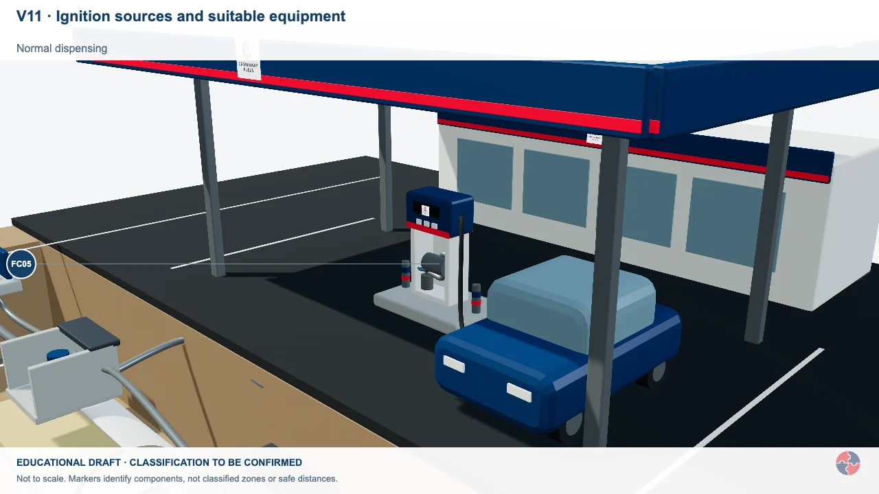
Ignition sources and suitable equipment
Electrical faults, hot work and other ignition sources matter where an explosive atmosphere could form.
Activity focus: Link equipment selection to the assessed atmosphere and actual dossier.
Contextual workplace scene. Use the task, control and evidence checks in this section; appearance alone does not establish safe conditions, individual health or approval.
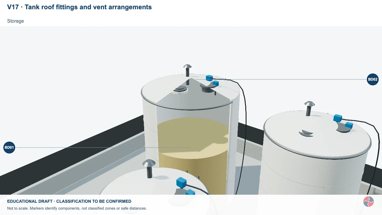
Tank roof fittings and vent arrangements
Normal tank breathing and emergency pressure relief serve different design purposes.
Activity focus: Locate the selected fittings and ask which design evidence supports them.
Contextual workplace scene. Use the task, control and evidence checks in this section; appearance alone does not establish safe conditions, individual health or approval.
Educational illustration, not to scale. Coloured zones are teaching examples, not a site-specific hazardous-area classification.
Only petroleum prevention/isolation; no implication that this model demonstrates dust suppression.
What training is needed for explosion prevention and protection?
Training should explain what the protection systems do, what they cannot do and what workers must do when a barrier is impaired.
Operators and supervisors need plain-language training on the specific controls at their site. They should know why dust layers matter, why a vent path must remain clear, why a suppression fault is serious, why hot work on empty vessels remains dangerous and why changes need review.
Maintenance and engineering teams need deeper training on inspection, proof testing, hazardous area equipment, relief devices, isolation devices, suppression systems and MOC. Specialist design should be carried out or verified by competent people.
| Role | Learning | Demonstration | Assessor | Record | Reassess when |
|---|---|---|---|---|---|
| Operator | Recognise release and stop points | Explain filter failure response | Shift lead | Briefing | Material change |
| Engineer | Define design limits | Trace vent/isolation path | Technical authority | Design file | Modification |
| Maintenance | Preserve safety devices | Show test and hand-back | Engineering lead | Work order | Defect |
| Supervisor | Control housekeeping and hot work | Inspect hidden areas | Site manager | Inspection | Accumulation |
| Emergency lead | Plan blast and fire response | Run scenario drill | Site lead | Exercise record | Plan change |
| Director | Resource barrier assurance | Trace impairments to decisions | Independent assurance | Review record | Backlog |
How does this topic support NEBOSH PSM study?
This topic supports NEBOSH PSM by showing how prevention, relief, isolation and suppression operate as major accident barriers.
A strong PSM answer should start with the scenario and then identify which controls prevent the explosion and which controls mitigate it. For example, in a combustible dust system, prevention may include dust containment, housekeeping and ignition control, while mitigation may include relief, isolation and suppression.
Scenario answers should also mention limitations. Explosion relief does not remove fire risk; suppression needs maintenance; isolation must match duct design; and all protection systems need MOC when materials, equipment or operating conditions change.
| Study point | What to explain | Scenario application |
|---|---|---|
| Prevention | Avoid explosive atmospheres and ignition. | Closed handling, ventilation and ignition control. |
| Relief | Designed pressure release to safe place. | Dust collector relief panel and exclusion zone. |
| Isolation | Stop propagation through connected plant. | Duct isolation valve or flap valve. |
| Suppression | Detect and suppress early explosion. | Pressure detector and suppressant bottles. |
| Design limitations | Protection only works within assumptions. | Review material and duct changes. |
| Assurance | Inspection, testing and impairment control. | Treat faults as safety critical. |
How do management frameworks support this topic?
HSE’s Plan–Do–Check–Act guidance helps assign ownership, deliver controls, check evidence and improve weak arrangements. Apply the relevant legal duties and task-specific technical evidence separately.
Official management guidance: HSE Managing for health and safety (HSG65)
| Framework | Status and scope | Contribution | Limit |
|---|---|---|---|
| HSE HSG65 | GB regulator management guidance | Plan, do, check and act with evidence of current control | Apply to the actual high-consequence scenario. |
What are the warning signs that explosion protection is failing?
Warning signs include blocked vents, impaired suppression, poor housekeeping, unreviewed changes, damaged hazardous area equipment and unclear ownership.
These warning signs are serious because they can defeat the engineered barriers people are relying on. If a vent is blocked, a relief system may not protect the vessel. If isolation is missing, an event can propagate. If suppression is faulty, pressure may rise beyond design expectations.
The response should be immediate and proportionate. Some impairments may require stopping the process until a competent person confirms safe operation or compensating measures.
| Warning sign | How it can cause harm | Response |
|---|---|---|
| Blocked relief panel | Explosion pressure cannot discharge as designed. | Stop, clear, inspect and review storage controls. |
| Suppression fault alarm | System may not activate on demand. | Apply impairment rule and specialist service. |
| Dust layers returning quickly | Primary or secondary explosion fuel remains. | Fix dust escape source and review LEV. |
| Material changed without review | Explosibility assumptions may be invalid. | MOC and technical reassessment. |
| Damaged ATEX equipment | Ignition source may be present. | Isolate and repair with competent inspection. |
| No owner for protection system | Inspection and maintenance may drift. | Assign owner and performance standard. |
| Vent discharge area occupied | People may be exposed to flame or debris. | Reassess layout and exclusion zone. |
Chemical hazard symbols: what do they mean?
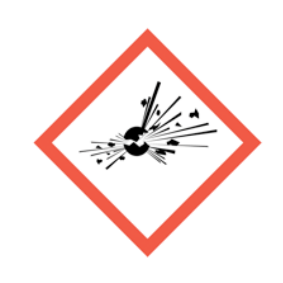
Exploding bomb
Explosive, self-reactive or organic peroxide hazards.
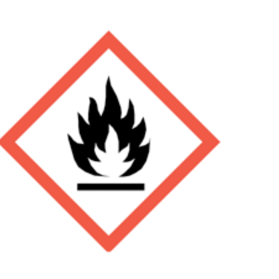
Flame
Flammable, self-heating or pyrophoric substances.
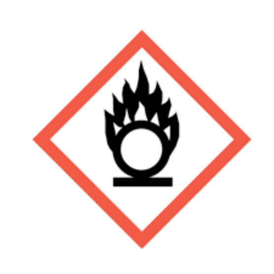
Flame over circle
Oxidising substances that can intensify fire.

Gas cylinder
Gas under pressure.
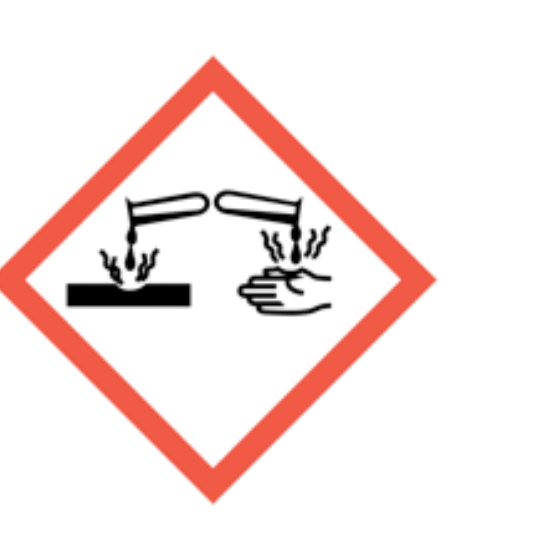
Corrosion
Skin burns, eye damage or corrosive to metals.
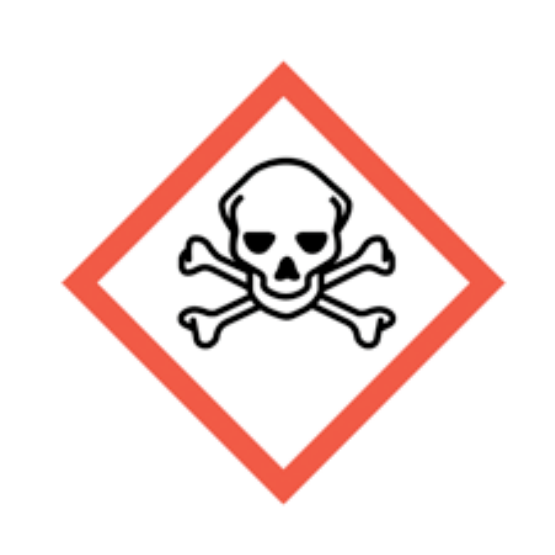
Skull and crossbones
Acute toxicity.

Exclamation mark
Irritation, harmful effects or skin sensitisation; some classifications cover drowsiness, dizziness or ozone-layer hazard. Read the actual hazard statements. Skin sensitisation differs from respiratory sensitisation.
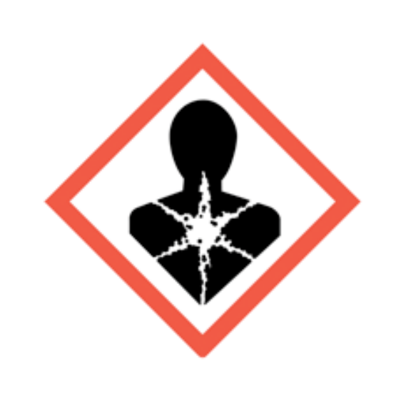
Health hazard
Serious health hazards, including organ damage, aspiration hazard, respiratory sensitisation, cancer and reproductive effects; some can follow a single exposure.
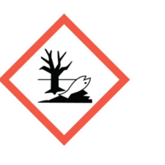
Environment
Hazardous to the aquatic environment.
What do the acronyms and key terms mean?
Acronyms should be defined so readers can understand protection systems and DSEAR language.
| Term | Meaning | Why it matters |
|---|---|---|
| ATEX | Equipment and protective systems for explosive atmospheres. | Relevant to equipment suitability. |
| DSEAR | Dangerous Substances and Explosive Atmospheres Regulations. | Core UK workplace fire and explosion risk law. |
| HAZ | Hazardous area zone. | Defines areas where explosive atmospheres may occur. |
| LEV | Local exhaust ventilation. | Controls dust, vapour or fume at source. |
| MOC | Management of change. | Prevents changes invalidating protection design. |
| SCE | Safety critical element. | Barrier whose failure could contribute to major accident risk. |
| VCE | Vapour cloud explosion. | A flammable vapour cloud explosion scenario. |
| Vent path | Route through which explosion pressure and flame are relieved. | Must remain unobstructed and safe. |
| Kst / Pmax | Dust explosion pressure-rise index / maximum explosion pressure. | Laboratory data for the actual material are part of specialist design; generic values are unsafe. |