SHARE Knowledge Hub
Pressure Relief, Venting and Emergency Depressurisation
Pressure relief, venting and emergency depressurisation protect a process when pressure or inventory could exceed safe limits. They are different functions: a relief device limits pressure in a defined scenario, a vent or disposal system carries the discharge safely, and emergency depressurisation may reduce inventory or escalation in an emergency. A device that opens at the right set point can still fail as a protective system if its inlet is blocked, the discharge is unsafe or the design basis no longer matches the plant.
Understanding Pressure Relief, Venting and Emergency Depressurisation
Pressure relief, venting and emergency depressurisation protect a process when pressure or inventory could exceed safe limits. They are different functions: a relief device limits pressure in a defined scenario, a vent or disposal system carries the discharge safely, and emergency depressurisation may reduce inventory or escalation in an emergency. A device that opens at the right set point can still fail as a protective system if its inlet is blocked, the discharge is unsafe or the design basis no longer matches the plant.
Why this matters at work
A relief device prevents one type of failure but can create toxic exposure, fire, explosion, burn, noise or environmental harm at its outlet. HSE relief guidance requires discharge to a safe location. That is a conclusion to be demonstrated for the actual substance, rate, phase, duration and meteorology, not a label attached to an atmospheric vent.
A control valve can fail open, fail closed, move to an unexpected position, pass through a bypass or lose motive power. The resulting relief rate depends on upstream inventory and pressure, valve characteristic, downstream response and whether another path limits flow. Crediting an alarm or operator action requires a demonstrated detection and response sequence; a normal control loop should not be assumed independent of the failure that creates demand.
How organisations manage this in practice
Identify digital functions credited in the relief basis and include them in functional-safety, alarm-management and cyber-security scope. Control logic, set point, timer, graphics, network and firmware changes with technical review and testing. Restrict access, maintain backups and verify recovery. For operator action credit, demonstrate alarm detectability, priority, available response time, workload, procedure and training. Record bypasses and standing alarms. Revalidate relief and depressurisation studies after control migration or remote-operation change, and retain a safe fallback for loss of digital services.
Use an approved workshop with competent personnel, controlled test equipment and traceable calibration. Provide the current data sheet and prohibit unapproved substitution. Review as-found set pressure, leakage, damage and deposits for implications beyond the individual valve. Confirm spring range, materials, orifice, direction and seals before release. Preserve traceability through transport and storage. On installation, verify tag, certificate, flange protection, set-point seal and correct location. Investigate repeated failures and feed evidence into interval, materials and process-control review.
Assign accountable leadership and competent technical authorities for process, mechanical, reaction hazards, control, inspection and environment. Sample devices from field tag back to calculation and from scenario forward to safe destination. Review overdue examinations, failed tests, isolated paths, model gaps, chronic lifting, flare events and temporary controls. Challenge whether resources and shutdown authority are adequate. Recheck sources and adopted standards on a planned cycle. Close findings only when plant, records and operating practice agree and the protection works for the current duty.
How can I practise this topic in 3D?

A proposed rapid valve closure ignores pipeline surge
Injection pressure and safe depressurisation
All related inspection points 7 across 2 locations
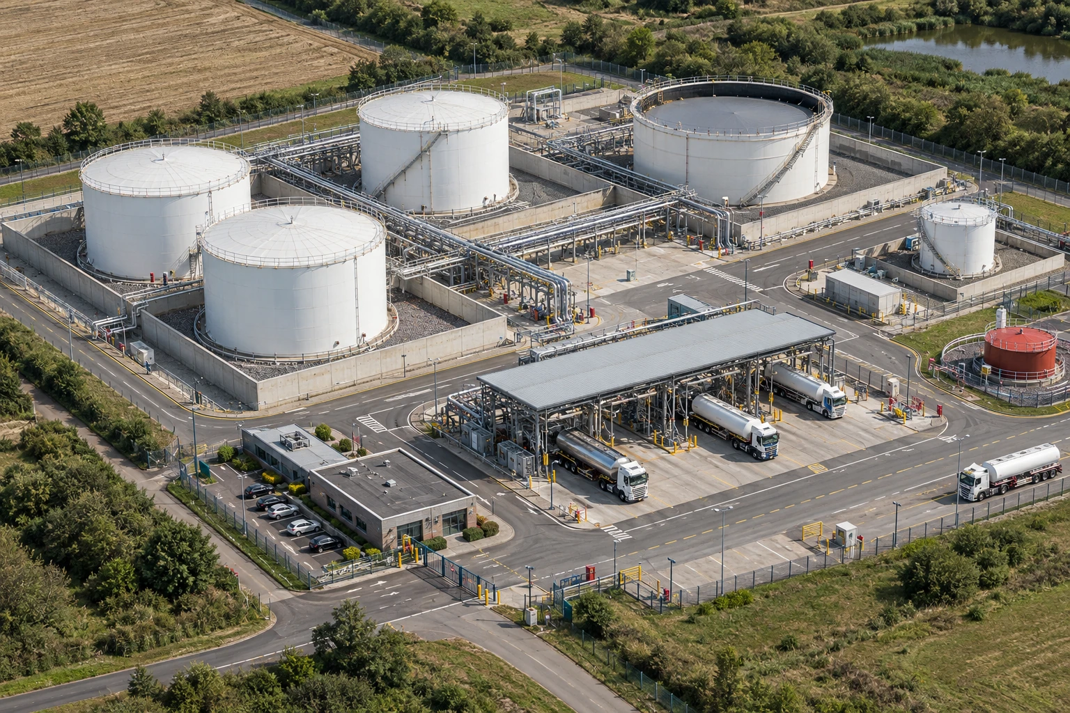
Crown Fuels terminal 6 inspection points
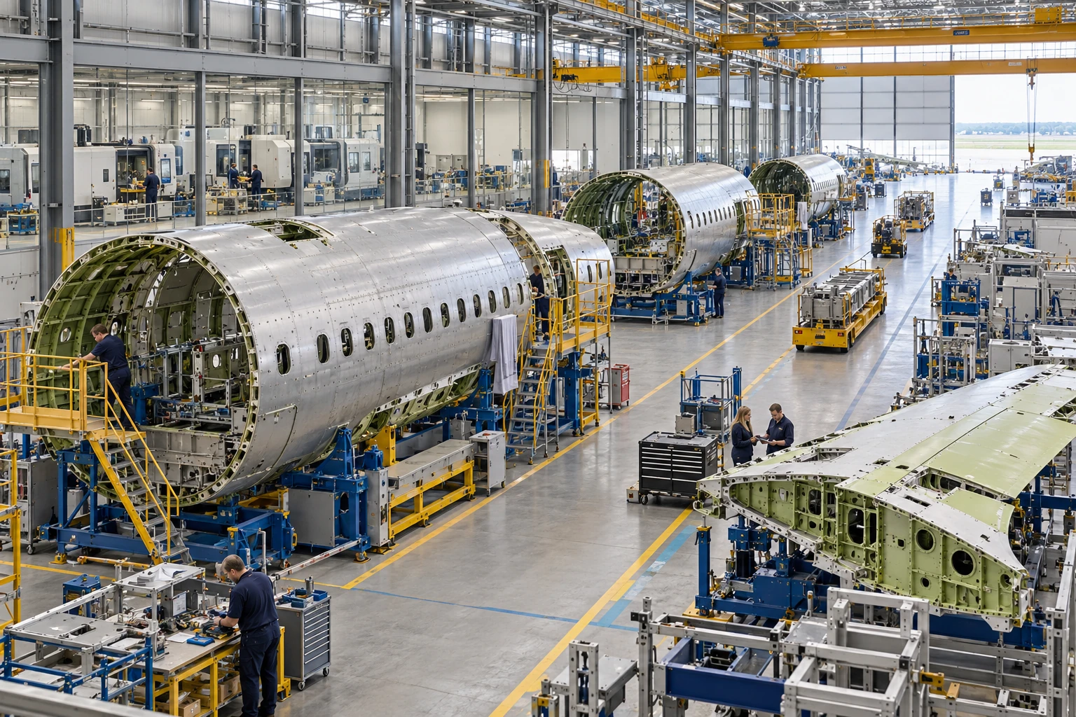
Aerosystems Engineering 1 inspection point
Practice in the SHAREhub environment. Browser practice is separate from workplace competence and formal learning records.
What are pressure relief, venting and emergency depressurisation?
They are engineered controls that prevent or reduce dangerous pressure and hazardous inventory during abnormal conditions.
Best-practice guide: Pressure Relief, Venting and Emergency Depressurisation
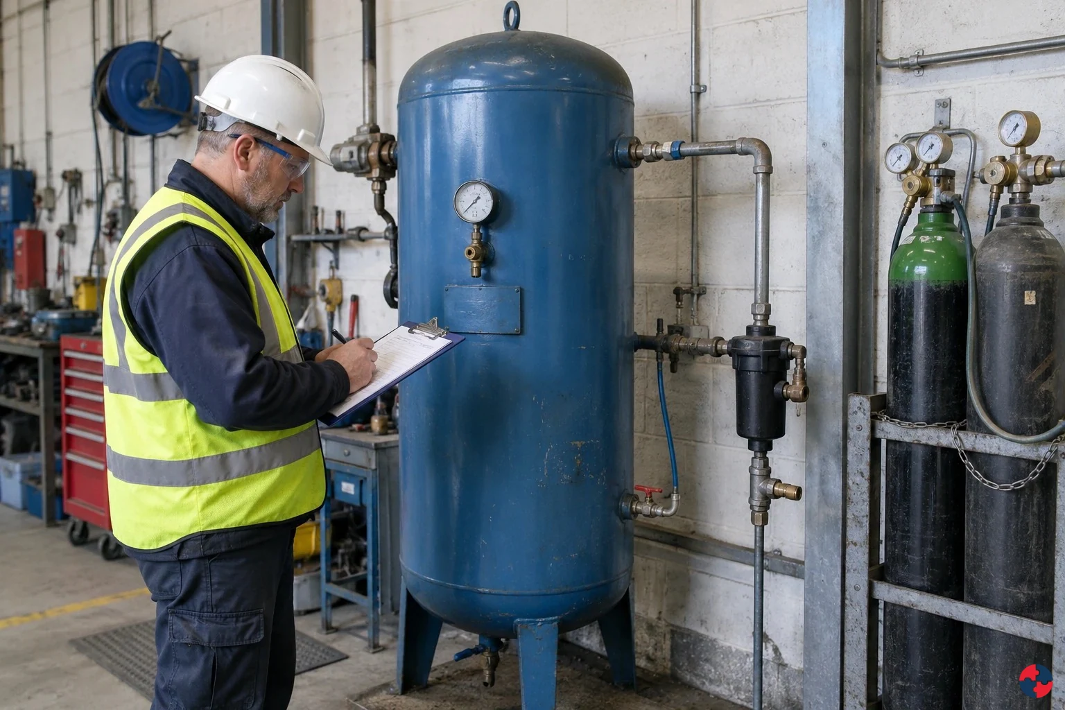
What are pressure relief, venting and emergency depressurisation?
The harm chain starts with excess pressure or inventory and a failed protective path: the vessel, pipe or seal can rupture, or a relief device can discharge to an unsafe place. Stored energy can cause blast and debris injuries; hot or cold fluid can burn; a toxic or oxygen-displacing release can harm through inhalation or asphyxiation; a flammable release can ignite. Pressure relief, venting and emergency depressurisation protect a process when pressure or inventory could exceed safe limits.
Turn pressure relief, venting and emergency depressurisation knowledge into a decision
Pressure relief, venting and emergency depressurisation protect a process when pressure or inventory could exceed safe limits. They are different functions: a relief device limits pressure in a defined scenario, a vent or disposal system carries the discharge safely, and emergency depressurisation may reduce inventory or escalation in an emergency. Management-of-change scope, LPG properties and scenario basis, vessel/relief calculations, flare study, proof-test records, lineup check, training and signed readiness release.
Operational example: LPG vessel change and relief evidence
Commission to a staged plan with verified alarms, shutdown logic, valve lineup and header capacity; monitor pressure and transfer rate against approved limits. Authorise the new operating envelope only after calculations, proof tests, procedures and outstanding safety-critical actions are accepted by the competent owners.
Where do relief and depressurisation systems commonly fail?
Failures often arise from assumptions, changes, impairments and poor evidence rather than from missing hardware alone.
Choose controls for pressure relief, venting and emergency depressurisation
Eliminate: Eliminate: the process designer removes a blocked-in liquid segment where possible by redesigning the transfer path and minimising dead legs. Reduce: Substitute and reduce: reduce hazardous inventory or choose lower-pressure operating conditions where the process permits. Isolate: Isolate and engineer: a competent engineer sizes the relief device, inlet and outlet for the governing scenario and routes discharge to a verified safe system. Control: Control, PPE and Discipline: use operating limits, change control, an impairment register and emergency instructions to keep engineered protection available. Read the full control table for qualifications, ownership and verification. Use the actual task and applicable jurisdiction; existing technical approval remains unchanged.
Use the full pressure relief, venting and emergency depressurisation lesson
Use the full topic for the decision points, practical examples, detailed control tables and source scope. HSE guidance applies to Great Britain; use HSENI for the Northern Ireland route and the source’s stated jurisdiction. A simplified guide does not change the page’s technical-review or approval status.

Read all six steps as text
1. What are pressure relief, venting and emergency depressurisation?
The harm chain starts with excess pressure or inventory and a failed protective path: the vessel, pipe or seal can rupture, or a relief device can discharge to an unsafe place.
- Avoid / redesign: Eliminate: the process designer removes a blocked-in liquid segment where possible by redesigning the transfer path and minimising dead legs.
- Control the task: Isolate and engineer: a competent engineer sizes the relief device, inlet and outlet for the governing scenario and routes discharge to a verified safe system.
- Verify before release: Read the full task example, checks and stop points on this page.
The harm chain starts with excess pressure or inventory and a failed protective path: the vessel, pipe or seal can rupture, or a relief device can discharge to an unsafe place. Stored energy can cause blast and debris injuries; hot or cold fluid can burn; a toxic or oxygen-displacing release can harm through inhalation or asphyxiation; a flammable release can ignite. Pressure relief, venting and emergency depressurisation protect a process when pressure or inventory could exceed safe limits.
Apply it: Which part of this plan would you check at the workface before authorising the task?
2. Turn pressure relief, venting and emergency depressurisation knowledge into a decision
Use the evidence to improve the actual work arrangement.
- Change at source: Eliminate: the process designer removes a blocked-in liquid segment where possible by redesigning the transfer path and minimising dead legs.
- Make it observable: Read the full task example, checks and stop points on this page.
- Keep useful evidence: Management-of-change scope, LPG properties and scenario basis, vessel/relief calculations, flare study, proof-test records, lineup check, training and signed readiness release.
Pressure relief, venting and emergency depressurisation protect a process when pressure or inventory could exceed safe limits. They are different functions: a relief device limits pressure in a defined scenario, a vent or disposal system carries the discharge safely, and emergency depressurisation may reduce inventory or escalation in an emergency. Management-of-change scope, LPG properties and scenario basis, vessel/relief calculations, flare study, proof-test records, lineup check, training and signed readiness release.
Apply it: What evidence would show that the change improves this task, rather than only completing a record?
3. Operational example: LPG vessel change and relief evidence
Example: a practical application of the existing topic lesson.
- Setting: the process operator proposes a higher transfer rate into a pressurised LPG storage vessel sharing a flare header with other protected equipment.
- Act: Revisit overfill, blocked outlet, external fire, thermal expansion, vapour-return failure and emergency blowdown against the changed throughput, vessel limits and common flare load.
- Hold / review: Do not start the higher-rate transfer if relief capacity, flare back-pressure, device availability, emergency depressurisation load or operator response is unresolved.
Commission to a staged plan with verified alarms, shutdown logic, valve lineup and header capacity; monitor pressure and transfer rate against approved limits. Authorise the new operating envelope only after calculations, proof tests, procedures and outstanding safety-critical actions are accepted by the competent owners.
Apply it: At which point would you hold this example, and what evidence would allow it to proceed?
4. Where do relief and depressurisation systems commonly fail?
Connect the task, the route to the person and the control that can fail.
- Source / exposure: Failures often arise from assumptions, changes, impairments and poor evidence rather than from missing hardware alone.
- Possible consequence: Common failures include relief valves isolated after maintenance, test dates overdue, incorrect set pressure, blocked vents, corrosion, fouling, undersized relief from old calculations, flare system changes not reviewed, rupture discs installed backwards, relief discharge near ignition sources, bypassed trips and operators unaware of emergency blowdown limits.
- Control failure: Auditors should challenge neat registers that do not match field condition.
Failures often arise from assumptions, changes, impairments and poor evidence rather than from missing hardware alone.
Apply it: Who could be exposed, including other trades, cleaners, maintainers and people nearby?
5. Choose controls for pressure relief, venting and emergency depressurisation
Start with the stronger practicable options and verify their effect.
- Eliminate: Eliminate: the process designer removes a blocked-in liquid segment where possible by redesigning the transfer path and minimising dead legs.
- Reduce: Substitute and reduce: reduce hazardous inventory or choose lower-pressure operating conditions where the process permits.
- Isolate: Isolate and engineer: a competent engineer sizes the relief device, inlet and outlet for the governing scenario and routes discharge to a verified safe system.
- Control: Control, PPE and Discipline: use operating limits, change control, an impairment register and emergency instructions to keep engineered protection available.
Eliminate: Eliminate: the process designer removes a blocked-in liquid segment where possible by redesigning the transfer path and minimising dead legs. Reduce: Substitute and reduce: reduce hazardous inventory or choose lower-pressure operating conditions where the process permits. Isolate: Isolate and engineer: a competent engineer sizes the relief device, inlet and outlet for the governing scenario and routes discharge to a verified safe system. Control: Control, PPE and Discipline: use operating limits, change control, an impairment register and emergency instructions to keep engineered protection available. Read the full control table for qualifications, ownership and verification. Use the actual task and applicable jurisdiction; existing technical approval remains unchanged.
Apply it: Which stronger option can be used here, and who will verify it before accepting the remaining risk?
6. Use the full pressure relief, venting and emergency depressurisation lesson
Follow the official sources below and retain the task-specific evidence.
- Official guidance: HSE relief and vent systems technical measures
- Official guidance: HSE safety of pressure systems L122
- Task decision: Management-of-change scope, LPG properties and scenario basis, vessel/relief calculations, flare study, proof-test records, lineup check, training and signed readiness release.
Use the full topic for the decision points, practical examples, detailed control tables and source scope. HSE guidance applies to Great Britain; use HSENI for the Northern Ireland route and the source’s stated jurisdiction. A simplified guide does not change the page’s technical-review or approval status.
Apply it: Which official source and full-topic section will you use to resolve the next decision?
Pressure relief is not just a valve on top of a vessel. It is a safety function with a design basis, credible scenarios, set pressure, capacity, materials, inlet and outlet pressure losses, discharge destination, inspection regime and impairment rules. Venting and emergency depressurisation add further questions: where does the material go, can the route safely handle it, could it ignite, could it harm people, and how quickly must inventory be reduced?
For learners, the simplest mental model is: pressure rises because normal control has failed or abnormal energy has entered the system; the relief or depressurisation system provides a controlled path to prevent catastrophic failure; the management system proves the path still works when needed. If any part of that chain is assumed rather than evidenced, the barrier is weak.
| Element | Purpose | Critical evidence |
|---|---|---|
| Pressure relief valve | Open at set pressure to relieve excess pressure. | Sizing basis, set pressure, test record, seal status and discharge route. |
| Rupture disc | Provide non-reclosing relief for defined overpressure scenarios. | Burst pressure, orientation, compatibility, inspection and replacement record. |
| Thermal relief | Protect blocked-in liquid from pressure rise due to heating. | Line list, isolation review, PSV coverage and MOC evidence. |
| Vent system | Route gas or vapour safely to atmosphere or treatment. | Dispersion, toxic/flammable assessment, location and restrictions. |
| Flare system | Dispose of flammable relief streams by combustion. | Flare capacity, knockout, pilots, radiation, smoke and maintenance evidence. |
| Emergency depressurisation/blowdown | Rapidly reduce inventory or pressure during fire or emergency. | Cause and effect, valve proof testing, timing basis and emergency procedure. |
Begin with the credible event, not a valve catalogue: fire exposure, blocked outlet, utility failure, thermal expansion, reaction or operator error may create different pressures and discharge states. A competent process engineer defines the scenario, fluid properties, required capacity and safe destination; operations verifies that installed isolation and maintenance state match the drawing. A rupture disc, relief valve, flare and emergency blowdown cannot be treated as interchangeable without that design basis.
Source: HSE relief and vent systems technical measures
Source: HSE safety of pressure systems L122
The harm chain starts with excess pressure or inventory and a failed protective path: the vessel, pipe or seal can rupture, or a relief device can discharge to an unsafe place. Stored energy can cause blast and debris injuries; hot or cold fluid can burn; a toxic or oxygen-displacing release can harm through inhalation or asphyxiation; a flammable release can ignite. These are different mechanisms and may invoke different legal controls. The stop point is before transfer or start-up when capacity, route, isolation or emergency response cannot be demonstrated. Source: HSE relief and vent systems technical measures
How can the hierarchy of controls prevent overpressure and control relief or depressurisation releases?
Eliminate, Reduce including substitution, Isolate, Control, personal protective equipment (PPE) and Discipline (ERICPD) is a prompt for decisions. HSE’s five-level hierarchy prioritises elimination, substitution, engineering controls, administrative controls and PPE. They are related frameworks, not identical laws; apply them to the actual task and check the resulting control.
Eliminate: the process designer removes a blocked-in liquid segment where possible by redesigning the transfer path and minimising dead legs. Review the design for new backflow or contamination routes; a removed scenario is stronger than a larger valve.
Substitute and reduce: reduce hazardous inventory or choose lower-pressure operating conditions where the process permits. Engineering verifies that the new fluid, throughput and reaction behaviour really reduce the relief case and do not create two-phase or polymerising discharge.
Isolate and engineer: a competent engineer sizes the relief device, inlet and outlet for the governing scenario and routes discharge to a verified safe system. Operations checks valve lineup; maintenance proves the device and records back-pressure, corrosion, blockage and isolation status. An open bypass, unproved device or changed flare header is a hold until the design basis is reconciled.
Control, PPE and Discipline: use operating limits, change control, an impairment register and emergency instructions to keep engineered protection available. Task PPE protects residual maintenance exposure only; it cannot make an undersized vent or unsafe discharge acceptable. The process owner stops a start-up when the relief path or scenario basis is uncertain and closes corrective actions with field evidence.
Source: HSE hierarchy of controls
Source: HSE relief and vent systems technical measures
How can the ERICPD hierarchy of controls prevent overpressure and control relief or depressurisation releases?

| ERICPD control level | Topic-specific example | Source and full task context |
|---|---|---|
| Eliminate | Remove a feasible pressure-generating scenario or unnecessary hazardous process inventory. | Read the full task example, checks and stop points on this page. HSE hierarchy of controls · HSE relief and vent systems technical measures |
| Reduce | No separate substitution is shown by lower pressure/inventory alone; assess a genuinely safer material/process replacement. | Read the full task example, checks and stop points on this page. HSE hierarchy of controls · HSE relief and vent systems technical measures |
| Isolate | Design and verify the protected system, relief device, inlet/outlet/header and safe disposal capacity. | Read the full task example, checks and stop points on this page. HSE hierarchy of controls · HSE relief and vent systems technical measures |
| Control | Control safe limits, changes, impairments, permits, handback and examination status through the competent route. | Read the full task example, checks and stop points on this page. HSE hierarchy of controls · HSE relief and vent systems technical measures |
| PPE | Select residual maintenance PPE; it cannot compensate for inadequate relief or an unlawful operating state. | Read the full task example, checks and stop points on this page. HSE hierarchy of controls · HSE relief and vent systems technical measures |
| Discipline | Verify lineup, tests and accepted release evidence; a senior signature cannot waive required protection. | Read the full task example, checks and stop points on this page. HSE hierarchy of controls · HSE relief and vent systems technical measures |
How can the ISO 45001 hierarchy of controls prevent overpressure and control relief or depressurisation releases?

| ESEAP control level | Topic-specific example | Source and full task context |
|---|---|---|
| Elimination | Remove a feasible pressure-generating scenario or unnecessary hazardous process inventory. | Read the full task example, checks and stop points on this page. HSE hierarchy of controls · HSE relief and vent systems technical measures |
| Substitution | No separate substitution is shown by lower pressure/inventory alone; assess a genuinely safer material/process replacement. | Read the full task example, checks and stop points on this page. HSE hierarchy of controls · HSE relief and vent systems technical measures |
| Engineering controls | Design and verify the protected system, relief device, inlet/outlet/header and safe disposal capacity. | Read the full task example, checks and stop points on this page. HSE hierarchy of controls · HSE relief and vent systems technical measures |
| Administrative controls | Control safe limits, changes, impairments, permits, handback and examination status through the competent route. | Read the full task example, checks and stop points on this page. HSE hierarchy of controls · HSE relief and vent systems technical measures |
| PPE | Select residual maintenance PPE; it cannot compensate for inadequate relief or an unlawful operating state. | Read the full task example, checks and stop points on this page. HSE hierarchy of controls · HSE relief and vent systems technical measures |
Which overpressure scenarios must be considered?
Relief protection is only credible when the design scenarios have been identified and kept current.
A relief device sized for one scenario may be inadequate for another. Common cases include blocked outlet, control valve failure, external fire, tube rupture, utility failure, runaway reaction, thermal expansion, gas breakthrough, liquid overfill, reverse flow, abnormal start-up and failure of cooling or agitation. Process safety reviews should ask which cases apply, which case governs capacity and whether plant changes have altered the answer.
This is where management of change becomes critical. A new feedstock, increased throughput, changed solvent, modified control valve, higher storage temperature, new tie-in or changed flare load can invalidate an old relief calculation. Relief basis documents should therefore be living process safety information, not archive material.
| Scenario | How pressure rises | What to verify |
|---|---|---|
| Blocked outlet | Flow continues into closed or restricted system. | Relief capacity, isolation practices and operating procedure. |
| External fire | Heat input vaporises contents and raises pressure. | Fire case sizing, emergency response and depressurisation need. |
| Thermal expansion | Blocked-in liquid expands as temperature rises. | Thermal relief on trapped liquid sections. |
| Runaway reaction | Heat/gas generation exceeds cooling/control. | Reaction relief basis, vent sizing and quench/emergency systems. |
| Tube rupture | High-pressure side enters lower-pressure equipment. | Relief capacity and isolation/interlock response. |
| Utility failure | Cooling, instrument air or power failure creates abnormal state. | Fail-safe positions and emergency operating procedures. |
| Overfill | Liquid enters vapour relief path or vent system. | Level trips, alarms, independent protection and disposal route. |
Include normal venting and underpressure/vacuum scenarios for relevant low-pressure storage. An overpressure-only review is incomplete, and explosion relief has different response assumptions. Keep competent design/manufacturer review; historic standard editions quoted in older guidance are not automatically current.
What is the relief-system journey from source to safe disposal?
The protection route must be understood from the equipment being protected through to final discharge.
A relief system can fail even when the relief device itself is correct. Inlet piping may create excessive pressure loss. Outlet piping may impose back pressure. A flare knockout drum may flood. A vent may discharge into an unsafe location. A relief valve may be isolated for maintenance and not reinstated. The system journey must therefore be checked end to end.
For a Diploma-level answer, do not say only that a PSV is fitted. Explain the protected equipment, credible scenario, relief device, inlet/outlet route, disposal, inspection, impairment control, emergency response and evidence that proves the barrier is available.
| Stage | Question | Evidence |
|---|---|---|
| Protected equipment | What vessel, pipework or equipment can overpressure? | Equipment register and design pressure. |
| Credible cause | Which scenario creates the relief demand? | Relief basis or hazard study record. |
| Relief device | Is type, set pressure and capacity suitable? | Calculation, datasheet and test certificate. |
| Inlet route | Can flow reach the device without excessive pressure loss? | Piping review and installation check. |
| Outlet route | Can discharge be handled without dangerous back pressure? | Outlet calculation and flare/vent capacity review. |
| Disposal | Where does material go and what hazards remain? | Flare, vent, scrubber, dispersion or radiation assessment. |
| Assurance | How is availability proven over time? | Inspection, test, seal, impairment and MOC records. |
How should venting and relief disposal be judged?
The discharge route is part of the protection system, not an afterthought.
A relief device that vents toxic, flammable, hot, cold or two-phase material into an unsafe location can convert overpressure protection into a different major accident scenario. Disposal assessment should consider people nearby, ignition sources, occupied buildings, drains, low points, wind, radiation, toxic exposure, noise, cold embrittlement, liquid carryover and environmental impact.
Flares, vents, scrubbers and blowdown systems have their own failure modes. A flare with failed pilots, liquid carryover, inadequate capacity or poor knockout is not a healthy barrier. A vent stack with poor dispersion may expose workers. A scrubber may not have the capacity, reagent or monitoring needed for the relief scenario.
| Disposal route | Typical use | Key questions |
|---|---|---|
| Atmospheric vent | Non-toxic, non-flammable or controlled low-risk releases. | Could people, ignition sources or intakes be exposed? |
| Flare | Flammable gas/vapour disposal. | Are pilots, capacity, knockout, radiation and smoke controlled? |
| Scrubber/absorber | Toxic or corrosive relief streams. | Is chemistry, capacity, monitoring and waste route suitable? |
| Blowdown drum | Liquid/vapour separation before vent/flare. | Could it overfill, foam, flood or pass liquid onward? |
| Closed relief header | Multiple relief sources to common disposal. | Could simultaneous loads exceed design or create back pressure? |
| Local discharge | Small equipment or benign fluid. | Is it still safe after process change or maintenance? |
What does emergency depressurisation need to achieve?
Emergency depressurisation reduces pressure or inventory fast enough to limit escalation without creating a worse release.
Emergency depressurisation is often used to reduce stored energy, fire exposure escalation or hazardous inventory. The system may be manual, automatic or linked to fire and gas logic. The design question is not simply 'does the valve open?' It is whether the depressurisation rate, disposal capacity, valve reliability, controls, alarms, operator response and emergency procedures match the credible scenario.
Too slow and the equipment may fail before pressure reduces. Too fast and low temperature, hydrates, brittle fracture, flare overload, liquid carryover, noise, vibration or downstream impact may create new risks. This is why blowdown systems require competent process safety and mechanical integrity review.
| Check | Why it matters | Evidence |
|---|---|---|
| Activation logic | Manual/automatic trigger must match emergency scenario. | Cause and effect chart and proof test. |
| Depressurisation rate | Must reduce pressure quickly enough without excessive consequences. | Design calculation and scenario basis. |
| Low-temperature effects | Rapid expansion can cool equipment and piping. | Materials review and low-temperature assessment. |
| Flare/disposal capacity | Large emergency loads can overload disposal systems. | Flare load study and simultaneous demand review. |
| Valve reliability | Emergency valves must move when demanded. | Proof testing and stroke records. |
| Operator action | Operators must know when and how to initiate or confirm blowdown. | Emergency procedure and drill records. |
Where do relief and depressurisation systems commonly fail?
Failures often arise from assumptions, changes, impairments and poor evidence rather than from missing hardware alone.
Common failures include relief valves isolated after maintenance, test dates overdue, incorrect set pressure, blocked vents, corrosion, fouling, undersized relief from old calculations, flare system changes not reviewed, rupture discs installed backwards, relief discharge near ignition sources, bypassed trips and operators unaware of emergency blowdown limits.
Auditors should challenge neat registers that do not match field condition. Relief systems are physical barriers; they need field verification, not only document review.
| Failure mode | How it develops | Control response |
|---|---|---|
| PSV isolated | Maintenance or temporary operation leaves block valve closed. | Car-seal/lock control, position checks and permit handback. |
| Out-of-date sizing | Plant throughput, fluid or operating envelope changed. | MOC trigger and relief basis review. |
| Blocked or fouled relief path | Polymer, corrosion, solids or ice restricts flow. | Inspection, heat tracing, flushing or design change. |
| Back pressure underestimated | Common header or flare load changes. | Hydraulic review and simultaneous relief assessment. |
| Wrong discharge location | Vent exposes people, intakes or ignition sources. | Dispersion/radiation review and route change. |
| Emergency valve fails to move | No proof test, sticking actuator or lost instrument air. | Proof testing, maintenance and fail-safe design. |
| Open actions accepted informally | Defects remain because production pressure dominates. | Demonstrated required protection and competent technical acceptance; senior authorisation cannot waive a dangerous defect, required relief function or statutory examination restriction. |
How might a pressure relief review work in practice?
A worked example shows how technical relief questions become operational decisions.
Crownway Fuels Ltd plans to increase transfer rate into a pressurised LPG storage vessel. The old relief calculation assumed a lower filling rate and a different fire case. The change also affects the common flare header and emergency depressurisation load. A weak review would update the operating procedure only. A competent review would treat this as management of change affecting safety-critical pressure protection.
The review should ask whether overfill, blocked outlet, external fire, thermal expansion, vapour return failure and emergency depressurisation are still within the protection envelope. It should confirm relief capacity, flare load, valve testing, operator alarm response, shutdown logic and emergency plans before authorising the change.
| Review step | Question | Evidence expected |
|---|---|---|
| Define change | What throughput, inventory, pressure or operating limit changes? | MOC scope and design intent. |
| Identify scenarios | Which overpressure cases are affected? | Relief basis review. |
| Check capacity | Can PSV/disposal route handle revised demand? | Sizing calculation and flare review. |
| Check controls | Are alarms, trips and emergency shutdown still adequate? | Cause and effect and proof-test evidence. |
| Check operation | Do operators understand new limits and emergency action? | Procedure, training and drill record. |
| Authorise | Are open actions safe to close after start or must they be closed first? | Readiness gate and action risk acceptance. |
Operational example: LPG vessel change and relief evidence
Task material and setting: Crownway Fuels Ltd proposes a higher transfer rate into a pressurised LPG storage vessel sharing a flare header with other protected equipment.
People and prerequisites: The process engineer owns revised scenarios and capacity; mechanical and instrumentation specialists check devices and trips; operations owns the lineup and start-up gate.
Before: Revisit overfill, blocked outlet, external fire, thermal expansion, vapour-return failure and emergency blowdown against the changed throughput, vessel limits and common flare load.
During: Commission to a staged plan with verified alarms, shutdown logic, valve lineup and header capacity; monitor pressure and transfer rate against approved limits.
Hold or stop: Do not start the higher-rate transfer if relief capacity, flare back-pressure, device availability, emergency depressurisation load or operator response is unresolved.
Completion and hand back: Authorise the new operating envelope only after calculations, proof tests, procedures and outstanding safety-critical actions are accepted by the competent owners.
Evidence: Management-of-change scope, LPG properties and scenario basis, vessel/relief calculations, flare study, proof-test records, lineup check, training and signed readiness release.
What evidence proves pressure protection is healthy?
Good assurance combines design evidence, field condition, maintenance records and live operational discipline.
A relief valve register is useful, but not enough. The evidence pack should show the design basis, device data, set pressure, last test, next test, inspection defects, isolation status, discharge route, linked trips, emergency procedure, MOC history and open actions. Sampling should include field checks: are valves sealed open, tags correct, vents unobstructed and discharge routes still valid?
Senior leaders should see pressure protection as a critical-control theme. Open defects, overdue inspections, repeated failed tests, temporary isolation, flare capacity constraints and MOC backlog should be visible in management review.
| Evidence | What good looks like | Weakness to challenge |
|---|---|---|
| Relief basis | Current scenarios, calculations and assumptions. | Old calculation with no MOC link. |
| Device register | Protected equipment, set pressure, capacity, test dates and status. | Register not reconciled to field. |
| Written scheme | Pressure equipment and protective devices covered. | Protective devices missing from scheme. |
| Proof/test records | Results reviewed and defects closed. | Pass/fail recorded without trend review. |
| Isolation/impairment record | Temporary impairments authorised with compensating controls. | PSV isolated without risk acceptance. |
| Emergency drill | Operators can execute depressurisation procedure. | Procedure exists but has not been practised. |
| MOC close-out | Relief implications checked before change. | Process changes made without relief review. |
What should a relief-system evidence pack contain?
A relief-system evidence pack should let a competent reviewer trace each safety function from design basis through to field condition and open defects.
This evidence pack is what turns pressure relief from an assumed safeguard into an auditable critical control. It should be organised by protected equipment and relief route so engineers, operators, maintenance teams and auditors can answer the same core questions: what scenario creates demand, what device or system responds, where does the discharge go, what can isolate or impair it, and what evidence proves it is available today?
For high-hazard sites, the pack should also link to management of change, open-action governance and emergency planning. If a relief calculation is current but a discharge route has changed, or a PSV is correctly tested but isolated by a closed block valve, the protection function is still weak.
| Evidence item | What it should contain | Why it matters |
|---|---|---|
| Design basis | Protected equipment, design pressure, operating envelope, fluid and governing assumptions. | Defines the limit the relief system must protect. |
| Relief scenario register | Blocked outlet, fire case, thermal expansion, runaway, tube rupture, overfill and other applicable cases. | Shows which credible demands have been considered. |
| Set pressure records | Set pressure, test results, certificate, seal status and next due date. | Proves the device should open at the intended pressure. |
| Inspection/test records | Overhaul, calibration, proof test, failed tests, repairs and defect history. | Shows ongoing integrity and failure trends. |
| Discharge destination | Vent, flare, scrubber, blowdown drum or local discharge route and hazard assessment. | Confirms the release route does not create uncontrolled harm. |
| Flare/vent review | Back pressure, capacity, simultaneous loads, pilots, knockout, dispersion, radiation or toxic consequence review. | Tests whether the downstream system can accept the relief demand. |
| Blocked isolation controls | Car seals, locks, valve position checks, permit rules and field verification. | Prevents the relief path being unintentionally defeated. |
| MOC records | Evidence that process, throughput, fluid, equipment or disposal changes triggered relief review. | Keeps old calculations from becoming false assurance. |
| Overdue defect actions | Risk ranking, temporary controls, owner, due date and senior risk acceptance. | Makes impaired pressure protection visible and governed. |
What do learners commonly confuse?
Pressure protection concepts are easy to memorise but harder to apply without scenario thinking.
| Confusion | Better explanation | Professional test |
|---|---|---|
| PSV equals safe | A PSV is one component; the relief path and disposal route also matter. | Can the full route handle the credible scenario? |
| Relief prevents the incident | Relief usually mitigates overpressure after an initiating event. | What prevention barriers failed first? |
| Venting is always safe | Venting can create toxic, flammable, hot, cold or environmental hazards. | Where does the material go and who could be exposed? |
| Depressurisation is just opening a valve | Rate, route, low temperature, disposal and operator action matter. | Is the blowdown basis proven? |
| Written scheme covers all | The written scheme must be matched to real equipment and protective devices. | Does field condition match the scheme? |
Which legal duties and standards are relevant?
Pressure protection sits across pressure systems law, process safety, DSEAR, equipment safety and major accident control.
| Duty or regulation | What it requires | How to apply it |
|---|---|---|
| Health and Safety at Work etc. Act 1974 | Requires risks to workers and others to be managed so far as reasonably practicable. | Use process safety controls, competence, supervision and assurance to prevent high-consequence events. |
| Management of Health and Safety at Work Regulations 1999 | Requires suitable risk assessment, arrangements, competence and review. | Define credible scenarios, controls, owners and assurance routines. |
| COMAH Regulations 2015 | Requires major accident hazards to be prevented and consequences limited. | Apply where major accident hazard sites must demonstrate safety management and barrier control. |
| DSEAR 2002 | Requires dangerous substances and explosive atmosphere risks to be eliminated or controlled. | Connect pressure relief, ignition control, venting, flare systems and emergency arrangements to dangerous substance scenarios. |
| Pressure Systems Safety Regulations 2000 | Requires safe pressure systems, written schemes and competent examination. | Check design limits, protective devices, written scheme coverage and defects. |
| PUWER 1998 | Requires work equipment to be suitable, maintained and used safely. | Apply to valves, trips, alarms, vents, interlocks, controls and safety-critical equipment. |
| Health and Safety at Work (Northern Ireland) Order 1978 | Apply the general health, safety and welfare duty to this work setting. | Assign the NI employer dutyholder to keep the relief/depressurisation task and affected people safe; record the protective-system decision. |
| Management of Health and Safety at Work Regulations (Northern Ireland) 2000 | Assess work risks and maintain preventive arrangements appropriate to the actual task. | Assess credible overpressure scenarios and keep preventive arrangements, owners and field checks current. |
| Control of Major Accident Hazards Regulations (Northern Ireland) 2015 | Use the NI major-accident prevention and safety-management route only for an in-scope establishment. | For an in-scope establishment, verify that relief and depressurisation barriers support the major-accident prevention and safety-management case. |
| Dangerous Substances and Explosive Atmospheres Regulations (Northern Ireland) 2003 | Assess and control fire and explosion risk from dangerous substances under the NI route. | Check whether a relief discharge can create an explosive atmosphere and control the ignition and exposure route. |
| Pressure Systems Safety Regulations (Northern Ireland) 2004 | Set safe operating limits, maintain protective devices and use a written scheme of examination where the system is in scope. | Confirm safe operating limits, protective-device condition and the written scheme/examination evidence before release. |
| Provision and Use of Work Equipment Regulations (Northern Ireland) 1999 | Keep work equipment suitable, maintained and inspected where required. | Check suitability, maintenance and required inspection of the valve, actuator and associated work equipment. |
Choose the law for the pressure system, hazardous fluid and work location. PSSR concerns stored pressure energy and examination where in scope; DSEAR and COMAH address different flammable or major-accident scenarios. NI has separate instruments. Guidance and voluntary standards are not statutory duties.
How should the control be managed and reviewed?
For a GB workplace, HSE guidance supports identifying the actual risk, taking practical protective steps and reviewing whether they work. Name the decision owner, check the control during the real task and correct a failed arrangement. Apply the separate Northern Ireland duties and guidance where the work is in NI.
GB management guidance: HSE managing health and safety
What competence and training are needed?
Competence must match the technical and operational risk of relief, venting and depressurisation decisions.
Training should be role-based. General awareness creates a baseline, but supervisors, managers, advisers and senior leaders need different levels of decision-making, verification and escalation competence.
| Role | What to demonstrate | Who checks | Record and reassessment |
|---|---|---|---|
| Operators and maintainers | Identify safe limits, route lineup, device isolation and the hold point. | Supervisor observes a simulated blocked outlet or open bypass. | Authorisation, test and handover; reassess after change or impairment. |
| Process and mechanical specialists | Demonstrate scenario sizing, two-phase and discharge review, and device integrity checks. | Competent technical lead independently reviews a real design case. | Calculation basis and technical sign-off; revisit on process change. |
| Supervisors and emergency leads | Challenge impaired protection, coordinate isolation and direct emergency response. | Process safety lead tests an upset scenario. | Drill and release record; reassess after incident or exercise. |
| Managers and auditors | Sample safety-critical barrier health, overdue tests and change closures. | Independent specialist reviews an assurance sample. | Action closure and trend review. |
Source context: HSE relief and vent systems technical measures
How could Crownway Fuels Ltd manage this in practice?

Crownway would manage pressure relief as a safety-critical barrier family with named ownership and assurance evidence.
In a fuel terminal, pressure protection may include LPG vessels, pumps, pipework, thermal relief, emergency shutdown, vents, flares and tanker transfer interfaces. Crownway would connect design basis, operating limits, maintenance and emergency planning rather than treating each relief valve as an isolated asset.
| Management element | How the business would manage it | Evidence to review |
|---|---|---|
| Define | Map protected equipment, scenarios and relief routes. | Relief basis register. |
| Control | Maintain PSVs, rupture discs, vents, flares and blowdown valves. | Inspection and proof-test records. |
| Verify | Field-check valve positions, tags and discharge routes. | Critical-control verification. |
| Manage change | Review relief impact before process or throughput change. | MOC relief checklist. |
| Escalate | Authorise impairments and open defects at the right level. | Risk acceptance and action tracker. |
Source context: HSE relief and vent systems technical measures
How do tank vents differ from other pressure-relief systems?
Trace the forecourt tank vent to its outlet and compare the separate depot roof-fitting concept. The scene does not establish relief capacity or a depressurisation design.
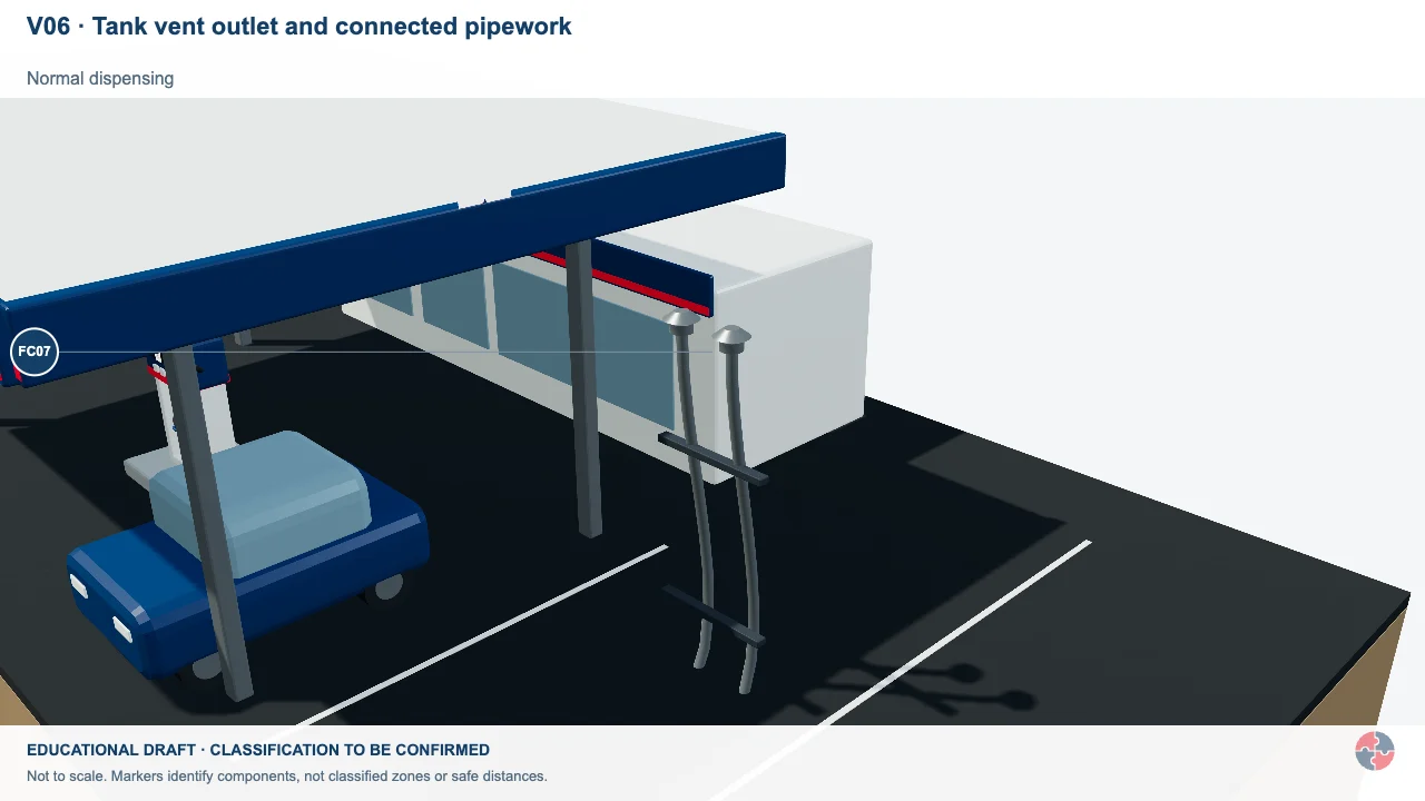
Tank vent outlet and connected pipework
Trace the tank vent from the vapour space to its outlet. The whole pipe is not a release boundary.
Activity focus: Check the outlet position and nearby openings when inspecting the assessment basis.
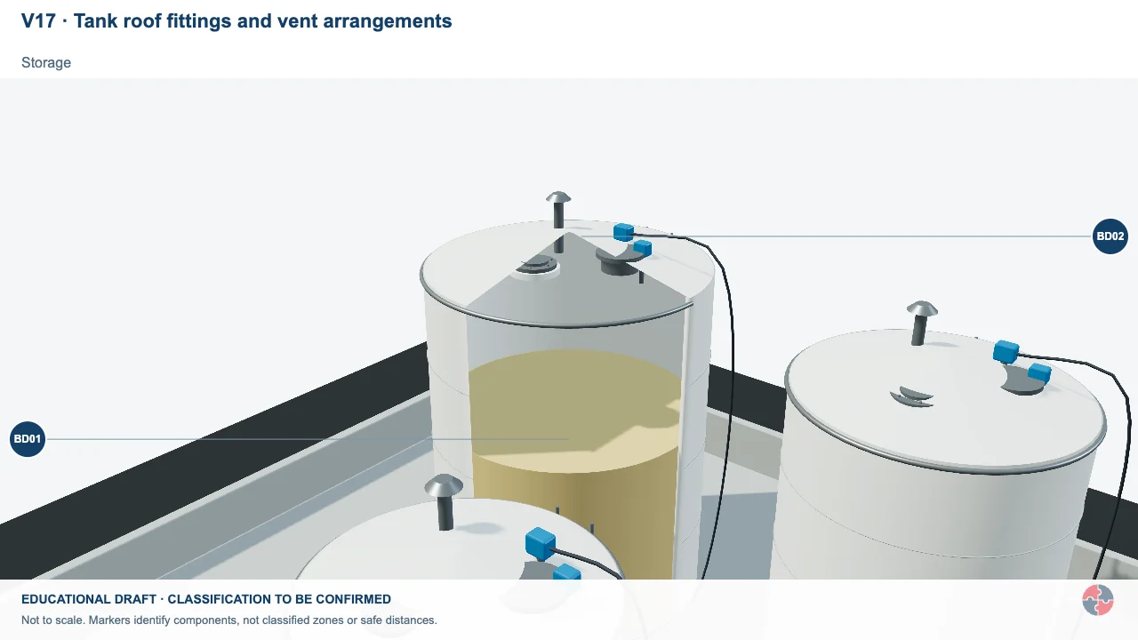
Tank roof fittings and vent arrangements
Normal tank breathing and emergency pressure relief serve different design purposes.
Activity focus: Locate the selected fittings and ask which design evidence supports them.
Educational illustration, not to scale. Coloured zones are teaching examples, not a site-specific hazardous-area classification.
Only relevant tank venting; do not imply reviewed emergency depressurisation equipment or procedure.
What do the acronyms and key terms mean?
Acronyms should be understood before they are used in assessments, briefings, audits or learning answers.
Acronyms can exclude newer readers if they are not explained. This section keeps the main terms available at the end of the page so the article stays readable while still supporting learners and audit users.
| Acronym | Meaning | Plain-English use |
|---|---|---|
| PSV | Pressure Safety Valve | Valve designed to open at a defined set pressure. |
| MAWP | Maximum Allowable Working Pressure | Maximum pressure permitted for equipment design. |
| MOC | Management of Change | Controlled review before changes are made. |
| PSSR | Pressure Systems Safety Regulations | UK pressure systems regulations. |
| COMAH | Control of Major Accident Hazards | UK major accident hazard regulations. |
Unlock another resource
You have used this month’s two free downloads. Publish a post in your own words to unlock one more resource, or choose SHARE Individual for 10 downloads per month.
You decide whether to share. If you do, use the relevant platform disclosure tools and do not make claims you do not genuinely hold.