SHARE Knowledge Hub
Electricity and static electricity
Electrical energy can injure people directly; static charge can also discharge into a flammable vapour or dust atmosphere. Transfer, filling, powders, plastics and insulating clothing can build charge even when equipment is otherwise electrically safe. Assess the actual substance and process, prevent a release, bond and earth suitable conductive parts, and verify those controls before transfer.
Understanding Electricity and static electricity
Electricity and static electricity are related but not interchangeable hazards. Electrical systems can cause shock, burns, arcing, fire and explosion. Static electricity is charge that can build up through contact, separation, flow, spraying, movement, filtration, mixing or handling of materials, then discharge. A static shock may startle a person, but its most serious workplace consequence is often a spark capable of igniting a flammable vapour, gas, mist or combustible dust atmosphere. The credible consequence can be a flash fire, explosion, burns, multiple casualties, toxic smoke exposure and major disruption.
Why this matters at work
Electricity can cause direct shock, burns, arcing, fire and explosion. A reported shock must not be classified as harmless static without competent assessment: a power-system fault may be involved. A static event can startle a person and cause secondary injury. A person can recoil into an edge, moving vehicle, machinery, hot surface or fall hazard. A static discharge may also damage a process-control or electronic system, creating indirect operational risk. Do not dismiss a reported shock without examining where, when and during what activity it occurred. Sources: HSE injury mechanisms; HSE static context.
Process failure: Process restarts before static and release barriers are restored | How control is lost: Uncorrected damage or impairment recreates ignition scenario | Possible consequence: Repeat fire/explosion, injury and escalation | Management measures assurance and recovery: Avoid: defer restart; Limit scope: reduce inventory and exposure; Restrict release: keep plant isolated/area controlled; Management arrangements: incident command, drill learning, impairment authorisation and functional verification; Residual task protection: residual PPE; Implementation assurance: restart authority confirms restored barriers and agreed emergency interfaces with competent evidence before release.
How organisations manage this in practice
The hierarchy is decisive. Eliminate the dangerous substance or dangerous process where reasonably practicable. If it cannot be eliminated, reduce quantity, hazardous properties, release, duration, dispersion, dust clouds, ignition exposure and people at risk. Use containment, closed transfer, suitable ventilation, separation, compatible layout, process control and safer operating states before relying on procedures. Then control static and other ignition sources with design, bonding/earthing, equipment selection, maintenance, zoning, supervision and competence.
Bonding connects conductive parts to limit potential differences between them. Earthing provides a path to earth where that forms part of the designed control. Their purpose in a static-control system is to manage charge on the relevant conductive equipment; they are not interchangeable words for attaching any clip to nearby metal. The entire path through vessels, hoses, couplings and fittings matters, including whether paint, corrosion, liners or insulating parts interrupt it. The competent procedure should identify approved connection points, connection sequence, verification, acceptance criteria, inspection and defect response. Train operators to recognise the correct arrangement and stop when a required connection or indication is uncertain. Do not invent a universal resistance value or test frequency for an unspecified installation. Keep proportionate evidence of the checks and repair or replacement decisions. Review changes to containers, coatings, hoses or the substance before use. A visible clamp may be useful evidence of placement, but only the specified verification can show that the intended control path is present.
Process failure: Static arrangements are not checked after change | How control is lost: Material, release or connection changes defeat an assumed barrier | Possible consequence: Ignition, fire, explosion, injury and enforcement | Management measures assurance and recovery: Avoid: stop changed/unknown process; Limit scope: limit material/exposure; Restrict release: isolate/contain/segregate; Management arrangements: MOC, DSEAR review, inspection, worker consultation and audit; Residual task protection: residual PPE; Implementation assurance: assurance owner reviews changed assumptions, recurring failures and action effectiveness at the workface before closure.
Separate shock protection from electrostatic ignition control
Shock protection protects people from current through the body. Electrostatic ignition control addresses charge accumulating and discharging into a flammable atmosphere. The controls overlap in places but answer different questions: a circuit RCD does not demonstrate that a powder or liquid transfer is protected from static ignition.
- Electric shock protection — Prevent contact and use suitable installation, protection and isolation.
- Liquid or powder transfer — Assess charge generation, flammable atmosphere and effective ignition.
- Bonding and continuity — Use the verified path and criteria in the competent process specification.
After Crownway changes product or fits an insulating hose, the operator holds transfer and asks the process owner to confirm the material, hose and receiving system against the approved method. The specialist checks charge-generating conditions, release control and the required continuity path and criteria. An earth clip, Ex label or isolated charge reading cannot authorise the changed transfer.
Content amended 19 October 2026 by the SHARE Knowledge Hub editorial team. This records an editorial content change; the existing technical-review and approval status still applies.
Assess charge generation and the complete transfer
Bonding conductive parts together and connecting to earth answer related but different questions. An insulating material can retain charge despite a nearby earth connection.
Separate the machine’s electrical risk from a static-ignition scenario
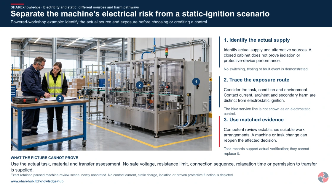
Full written explanation
Powered-workshop example: identify the actual source and exposure before choosing or crediting a control.
- Identify the actual supply. Identify actual supply and alternative sources. A closed cabinet does not prove isolation or protective-device performance.
- Trace the exposure route. Consider the task, condition and environment. Contact current, arc/heat and secondary harm are distinct from electrostatic ignition.
- Use matched evidence. Competent review establishes suitable work arrangements. A machine or task change can reopen the affected decision.
Change the pathway
- No visible status proof. No switching, testing or fault event is demonstrated.
- Do not merge the mechanisms. The blue service line is not shown as an electrostatic control.
- A plan is not a result. Task records support actual verification; they cannot replace it.
Evidence check: Use the actual task, material and transfer assessment. No safe voltage, resistance limit, connection sequence, relaxation time or permission to transfer is supplied.
Distinct electrical exposure and electrostatic charge/discharge mechanisms
Primary references: HSE: electrical injuries and separate mechanisms · HSE: flammable-liquid handling and static ignition
Open the complete HD image (new tab)Download image

Distinct electrical exposure and electrostatic charge/discharge mechanisms
Primary references: HSE: electrical injuries and separate mechanisms · HSE: flammable-liquid handling and static ignition

Identify the system
Establish materials, equipment, transfer conditions and the relevant flammable-atmosphere scenario.
Distinguish the safeguards
Assess bonding, earthing and charge generation/relaxation for the whole system, with appropriate competent advice and verification.
Control change
Treat a changed material, hose, container or transfer condition as a reason to reassess rather than copy the previous arrangement.
No resistance value, connection sequence or universal relaxation time is specified.
Where can static charge complete an ignition chain?
A moving liquid, powder or plastic can separate charge; a discharge is hazardous when a flammable atmosphere and an effective ignition path coincide.
At a fuel transfer, a disconnected bond or splash filling can raise the ignition risk. Operations must verify the product, zone, conductive path and release controls before transfer; a charge reading or generic bond label alone is not permission.
What are the key points about electricity and static electricity?
The key points are that supplied electricity can injure directly, while static electricity can become an ignition source when charge discharges in the wrong atmosphere.
What are the key points about electricity and static electricity? — part 1 of 3


Read the complete visual as text
- The key points are that supplied electricity can injure…: The key points are that supplied electricity can injure directly, while static electricity can become an ignition source when charge discharges in the wrong atmosphere.
- Treat electricity as stored or supplied energy: Fixed wiring, tools, batteries, chargers and test equipment can harm people when live parts or faults are uncontrolled.
- Treat static as an ignition pathway: Static discharge becomes critical where flammable vapour, gas, mist or combustible dust could be present.
What are the key points about electricity and static electricity? — part 2 of 3


Read the complete visual as text
- Understand charge generation: Flowing liquids, powders, belts, plastics, clothing, filters, splash filling, pneumatic transfer and people moving can all generate charge.
- Bonding and earthing are not decorative: Clips, cables and continuity checks must be suitable, connected, maintained and verified.
What are the key points about electricity and static electricity? — part 3 of 3


Read the complete visual as text
- Control the atmosphere as well as the spark: Good DSEAR control reduces releases, vapour build-up, dust clouds and ignition sources together.
- Evidence matters: Inspection records, permits, risk assessments, continuity checks, Ex equipment registers and defect closure prove controls exist beyond paperwork.
Treat electricity as stored or supplied energy
Fixed wiring, tools, batteries, chargers and test equipment can harm people when live parts or faults are uncontrolled.
Treat static as an ignition pathway
Static discharge becomes critical where flammable vapour, gas, mist or combustible dust could be present.
Understand charge generation
Flowing liquids, powders, belts, plastics, clothing, filters, splash filling, pneumatic transfer and people moving can all generate charge.
Bonding and earthing are not decorative
Clips, cables and continuity checks must be suitable, connected, maintained and verified.
Control the atmosphere as well as the spark
Good DSEAR control reduces releases, vapour build-up, dust clouds and ignition sources together.
Evidence matters
Inspection records, permits, risk assessments, continuity checks, Ex equipment registers and defect closure prove controls exist beyond paperwork.
What does electricity and static electricity mean in workplace safety?
Electricity is controlled energy in systems or equipment; static electricity is charge imbalance that can discharge suddenly.
Electricity in a workplace includes fixed installations, switchgear, control panels, machinery circuits, portable tools, chargers, batteries, test equipment and temporary supplies. The key safety question is whether a person can contact live parts, whether a fault can release energy, and whether the system is suitable, maintained and used correctly.
Static electricity is not supplied by a socket. It develops when materials separate, rub, flow, spray, pour, filter, mix or move. The charge may remain on a surface, container, liquid, powder, person or item of plant until it finds a discharge route. In low-risk settings this may be a small snap; in explosive atmospheres it may provide ignition.
| Aspect | Electricity | Static electricity |
|---|---|---|
| Energy source | Supplied or stored electrical energy. | Charge build-up from movement, separation or flow. |
| Typical harm | Shock, burns, arc flash, fire and secondary injury. | Spark ignition, startle, minor shock or process upset. |
| Main controls | Isolation, protection, equipment suitability and competence. | Bonding, earthing, antistatic equipment and atmosphere control. |
| Key evidence | Inspection, testing, isolation and maintenance records. | DSEAR assessment, continuity checks and transfer procedure. |
How does static electricity build up?
Static electricity builds up when materials transfer charge faster than the charge can dissipate safely.
Charge generation is common in industrial work because materials are constantly moving. Liquids flowing through pipes, fuels splashing into tanks, powders entering silos, plastic liners being handled, conveyor belts moving, synthetic clothing rubbing and filters separating droplets can all create charge.
Charge accumulation is more likely where materials are insulating, equipment is not conductive, humidity is low, flow rates are high, containers are plastic, pipework is isolated by gaskets or hoses, or bonding clips are missing. The risk is not simply that charge exists; it is that a charged object discharges where an ignitable atmosphere is present.
| Activity | Why charge forms | Risk example |
|---|---|---|
| Splash filling | Liquid breaks up and separates from air or surfaces. | Flammable vapour in a tank headspace. |
| High-velocity liquid transfer | Friction and separation occur through hoses, filters and pipework. | Fuel transfer without bonding. |
| Powder handling | Particles rub against each other and equipment. | Combustible dust cloud near ignition source. |
| Plastic liner handling | Insulating material can hold charge. | Static spark during solvent or powder handling. |
| Pneumatic conveying | Particles and air move rapidly through pipework. | Dust cloud ignition in collection equipment. |
| People movement | Footwear, flooring and clothing can generate charge. | Operator discharges near flammable vapour. |
Static charge is generated by contact and separation of materials, then accumulates where it cannot dissipate. The ordinary brief shock from a carpet is not the controlling concern here; a discharge can ignite a hazardous atmosphere during transfer or powder handling. See HSE HSG140 safe use and handling of flammable liquids.


How do moving materials separate charge and allow static to accumulate?
Contact and separation can leave materials with opposite charge imbalances. Moving material can carry charge onward. Accumulation becomes possible when charge arrives faster than it dissipates; charging and accumulation are different stages.
Read the complete lesson without the viewer
A transfer-line cutaway follows paired charge markers through contact, separation and transport, then compares connected and isolated conductive components.
FS10 · Charge generation and accumulation
Contact and separation can leave materials with opposite charge imbalances. Moving material can carry charge onward. Accumulation becomes possible when charge arrives faster than it dissipates; charging and accumulation are different stages.
Industrial charge generation describes separation or transfer of existing charge, not creation of new charge. The example separates interface charging, transport, redistribution within metal and dissipation along a continuous conductive route. A conductive fitting can still accumulate charge when isolated. Actual carriers and polarity depend on the materials. No discharge is needed to demonstrate accumulation.
Eight named structures and concepts
FS10-H01 · Contact interface
The two materials meet here. Paired abstract signs explain a possible separation mechanism; charge does not appear from nothing.
FS10-H02 · Separation zone
The contacting regions move apart. Opposite imbalances remain traceable across the two sides of the inset.
FS10-H03 · Moving material
Material motion can transport charge. Flow arrows identify material movement and are different from the charge-dissipation arrows.
FS10-H04 · Conductive fitting
Charge can redistribute within the metal. Conductivity alone does not connect this fitting to earth.
FS10-H05 · Insulating support
This support interrupts the drawn conductive route. The material boundary explains why internal metal conductivity does not guarantee dissipation.
FS10-H06 · Continuous dissipation route
A connected conductive path permits charge relaxation. Trace every connected component to the earth reference; the drawing makes no numerical performance claim.
FS10-H07 · Remaining imbalance
Arrival and dissipation can leave different amounts of net charge. The overlay is qualitative; it is not voltage, stored energy or a calculated ignition risk.
FS10-H08 · Charge-balance legend
Plus and minus signs mean charge imbalance. They are not hot particles, chemical fuel or a visible stream of electrons in the liquid.
Four illustrative states
Contact
Magnify the interface and identify paired markers without a spark or flame.
Separation and transport
Follow the opposing regions apart, then carry material-associated markers downstream.
Opposing charge separates Follow the paired signs as the contact surfaces separate.
Charge travels with material The same negative markers move downstream; no new charge is created by the animation.
Compare the paths
Trace the connected conductor and compare it with the fitting on an insulating support.
Follow the connected route Two markers move along the connected path towards the earth reference.
Compare the isolated fitting The isolated metal retains its markers. Conductive material still needs an effective connection.
Compare accumulation
Observe different remaining imbalances. The sequence stops before discharge.
Does a metal fitting automatically avoid static-charge accumulation?
Yes, because metal conducts Conductivity and connection are separate properties. Check the complete route away from the fitting.
No, it can accumulate charge if electrically isolated Correct. Charge can redistribute inside metal while an interrupted external path limits dissipation.
HSE — Earthing · HSE — Preventing dust explosions in the food industry · HSE — Safe handling of combustible dusts: Precautions against explosions
Sources, original geometry and review status
Original editable procedural geometry and illustrations. No third-party fire artwork, atlas, site model or incident footage is copied. Sources establish scientific context; the depiction requires competent scientific and editorial review. Three.js is supplied under its MIT licence.
FS10 HSE — Earthing · HSE — Preventing dust explosions in the food industry · HSE — Safe handling of combustible dusts: Precautions against explosions
No material-specific values have been added. Missing product, method and conditions remain unverified. This library gives no site approval, prediction or practical certification.
When can static electricity ignite an atmosphere?
Static electricity can ignite an atmosphere when a charged object discharges enough energy into a flammable vapour, gas, mist or combustible-dust cloud.
Ignition needs the right combination: fuel, oxygen, a flammable concentration and sufficient ignition energy. Static electricity is therefore most serious where dangerous substances are transferred, stored, mixed, sprayed, cleaned, poured, dispensed or released. The control strategy should prevent explosive atmospheres where possible and control electrostatic discharge where they could still occur.
This is why static control belongs in DSEAR assessments. A risk assessment that lists flammable liquid but never asks how filling, filtering, pumping, sampling, cleaning or container choice could generate charge is incomplete. See HSE electricity in potentially explosive locations.
| Scenario | What can fail | Barrier focus |
|---|---|---|
| Filling a metal drum with solvent | No bonding between container, drum and transfer equipment. | Bonding, earthing and controlled fill rate. |
| Pouring flammable liquid into plastic container | Container may accumulate charge and be unsuitable. | Use suitable conductive or antistatic containers. |
| Powder transfer to silo | Dust cloud forms and charge accumulates. | Explosion prevention, bonding and dust control. |
| Spray application | Mist/vapour and charge generation occur together. | Ventilation, Ex equipment and antistatic controls. |
| Sampling from tank | Vapour space may be flammable. | Procedure, waiting time and suitable equipment. |
| Cleaning with solvent | Flammable vapour and synthetic materials may be present. | Substitution, ventilation and ignition-source control. |
How do shock, burns and arc flash fit into this topic?
Shock, burns and arc flash remain part of the topic because workplaces must manage both direct electrical injury and static ignition.
A page on electricity and static electricity should not reduce electricity to static sparks. People can still be killed or badly injured by direct contact with live parts, faulty equipment, exposed conductors, unsafe testing, damaged chargers, wet tools, temporary supplies and battery systems.
The difference is the risk pathway. Shock and burns usually involve current passing through or near a person. Arc flash involves fault energy being released through air. Static electricity may involve a person, liquid, powder or item of plant becoming charged and then discharging into an ignitable atmosphere.
| Mechanism | How it occurs | Control principle |
|---|---|---|
| Electric shock | Current passes through the body. | Prevent contact and isolate before work. |
| Electrical burns | Current or fault heat damages tissue. | Control energy and avoid live work. |
| Arc flash | Fault energy travels through air. | Competent work, barriers and safe equipment. |
| Electrical fire | Overload, arcing or overheating ignites materials. | Maintenance and load control. |
| Secondary injury | Shock causes fall, impact or rescue exposure. | Plan work location and emergency response. |
For direct shock and burn mechanisms, see HSE electrical injuries; for safe electrical working, see HSE HSG85.
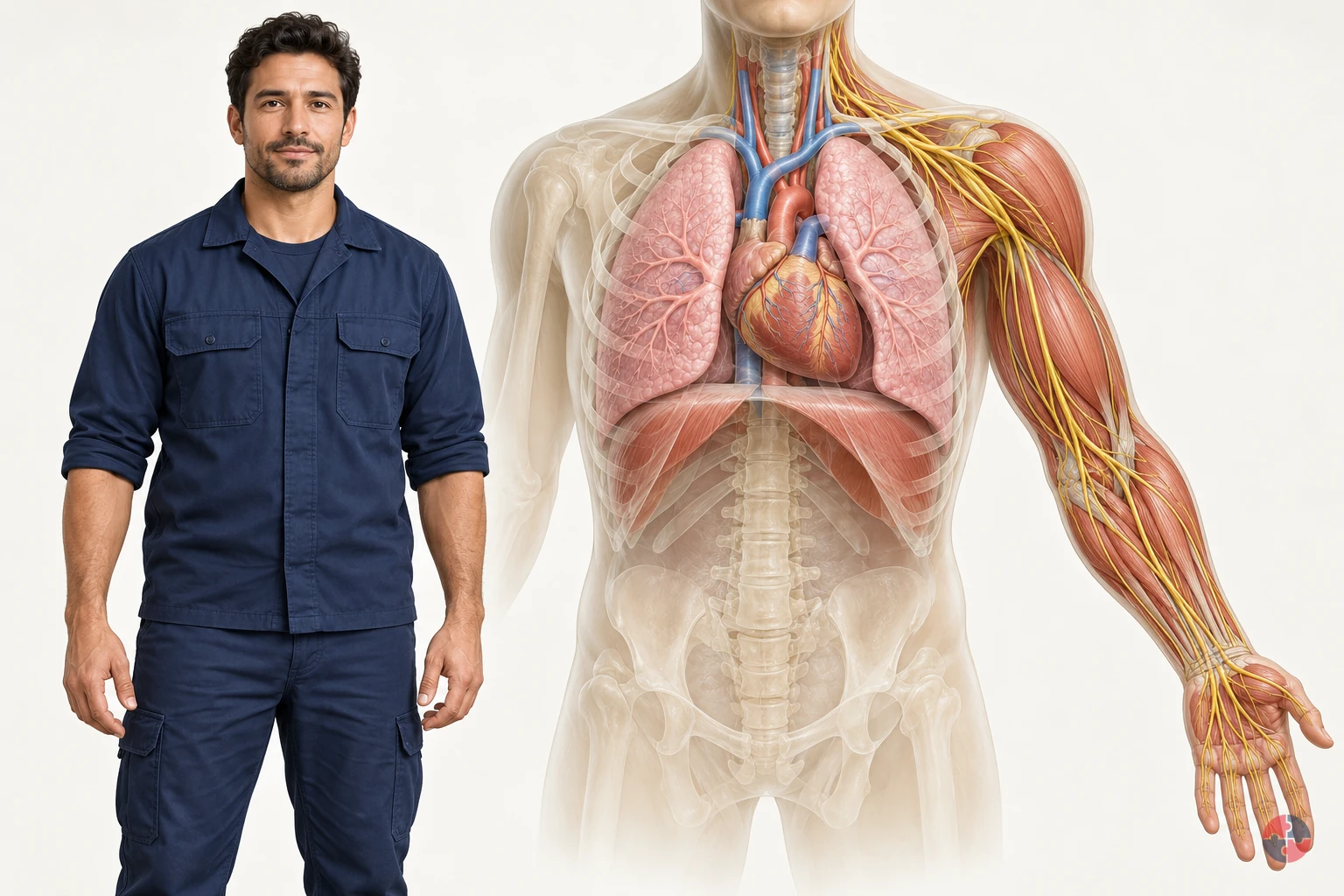
How can electricity injure the body, and why can a small mark hide a serious incident?
Interactive anatomy · Electrical injury · Updated 2026-10-23
Electrical injury terms
A broad term for injury associated with electrical exposure.
An external current affecting the body.
Tissue injury caused by electrical heating.
Death from electric shock.
Health and Safety Executive: Electrical injuries · Health and Safety Executive: Selection and use of electric handlamps, PM38 · NHS: Burns and scaldsRead all anatomy and process explanations without the viewer
General occupational awareness of anatomy and incident mechanisms. A broad term for injury associated with electrical exposure. An external current affecting the body. Tissue injury caused by electrical heating. Death from electric shock. Electrical rescue, live testing, isolation or energised work instruction An energise-person control, contact timer, voltage or resistance input Safe current paths, survival percentages or shock-severity scores ECG interpretation, rhythm selection or AED shock decisions Medical or workplace clearance from a mark, diagram or feeling well The hazard-avoidance and medical-help panel is visible before model loading and quiz completion.
Nerve pathway
Nerves communicate using electrical and chemical signals. Nerves carry biological signals, and communication at the nerve-to-muscle connection helps activate muscle. The travelling cue is a simplified way of directing attention to that relationship. It does not show household current circulating through a person, and its colour, speed or brightness cannot be used to interpret nerve function or electrical injury. Alder Hey Children’s NHS Foundation Trust: Nerve service — normal nerve function · NHS: Lambert-Eaton myasthenic syndrome — normal nerve-to-muscle signalling · Oxford University Hospitals NHS Foundation Trust: Nerve Conduction Studies and Electromyography
Skeletal muscle
The nervous system normally coordinates muscle contraction. A slow hand movement demonstrates normal function; it does not imitate a casualty’s involuntary movements. Alder Hey Children’s NHS Foundation Trust: Nerve service — normal nerve function · NHS: Lambert-Eaton myasthenic syndrome — normal nerve-to-muscle signalling
Breathing muscles
Coordinated muscle activity helps move air into and out of the lungs. The diaphragm and chest movement belong to the respiratory lesson. This example shows no breathing-rate measurement. Cambridge University Hospitals NHS Foundation Trust: Breathing pattern disorders and physiotherapy — normal diaphragm role
Heart conduction
Coordinated electrical activity helps organise the heart’s pumping. A labelled sequence illustrates normal biological activation. It is not an ECG or a rhythm-interpretation exercise. St George’s University Hospitals NHS Foundation Trust: Catheter Ablation for Supra-Ventricular Tachycardia — normal electrical system · NHS 111 Wales: Cardiac Arrest
Skin contact region
Contact conditions influence how an electrical exposure affects the body. The marker identifies an example contact region. It does not calculate skin resistance or identify a safe point to touch. Health and Safety Executive: Electrical injuries · Health and Safety Executive: Electrical safety frequently asked questions
Internal tissue region
Electrical injury can extend beneath the visible surface. An electrical incident can cause effects below the surface, so visible appearance alone cannot describe the whole injury. This transparent region marks the subject of the explanation, rather than a measured boundary of damage. Its shape does not establish where current travelled or which tissues are unaffected; compare it with the selected mechanism caption. Health and Safety Executive: Electrical injuries · NHS: Burns and scalds · NHS 111 Wales: Burns and scalds — electrical burns
External source
The incident hazard comes from an electrical source outside the body. The generic equipment symbol is kept disconnected from the normal biological signalling diagram. Health and Safety Executive: Introduction to electrical safety
Illustrative exposure route
This broad region represents one possible exposure route. It cannot establish the actual route or outcome. There is no safe-path selector, voltage control or timed-contact exercise. Health and Safety Executive: Electrical injuries · Health and Safety Executive: Electrical safety frequently asked questions
Arc and thermal region
An arc or hot electrical equipment can cause injury. This separate incident panel is different from a simple through-body current diagram. No arc flash is animated. Health and Safety Executive: Electrical injuries · Health and Safety Executive: Introduction to electrical safety
Secondary injury
Loss of control can lead to falls or contact with nearby hazards. The neutral surrounding-hazard symbol recognises these injuries without staging a fall or body jerk. Health and Safety Executive: Electrical injuries · Health and Safety Executive: Introduction to electrical safety
Response boundary
Keep clear of unresolved electrical danger and get emergency help. Do not touch a person who may still be in contact with an electrical source. This node opens the safety panel, never a rescue activity. Health and Safety Executive: Introduction to electrical safety · Health and Safety Executive: Electricity — electric shock and overhead-line precautions · Health and Safety Executive: Emergency procedures
Open the complete process transcript
The process, step by step
Explore normal function
Start with the body’s own signalling: nerves communicate with muscles, breathing muscles move the chest, and organised activation coordinates the heart. Select one example at a time and read the associated label before changing systems. These are normal biological functions, not electricity from equipment moving through a person. The slow cues make the explanation easier to follow; they do not show a measured nerve signal, breathing rate or heart rhythm. This process sequence is a teaching route through the subject, not a simulation of an electrical accident. Alder Hey Children’s NHS Foundation Trust: Nerve service — normal nerve function · NHS: Lambert-Eaton myasthenic syndrome — normal nerve-to-muscle signalling · Cambridge University Hospitals NHS Foundation Trust: Breathing pattern disorders and physiotherapy — normal diaphragm role · St George’s University Hospitals NHS Foundation Trust: Catheter Ablation for Supra-Ventricular Tachycardia — normal electrical system
What to watch: Select the nerve, skeletal-muscle, breathing-muscle and heart labels individually, noticing that each belongs to a different normal biological example.
Why it matters: Normal signalling helps muscles work in a coordinated way. Keeping these biological examples distinct from the incident diagrams makes it easier to explain what an external electrical hazard can disrupt.
Explore this step: Explore one normal system, then explain its function before selecting a different system.
Locate the external hazard
Locate the generic electrical-source symbol outside the body and compare it with the normal biological labels. It represents an external workplace hazard, not the source of ordinary nerve or heart signalling. The model keeps the equipment symbol separate and does not energise the silhouette when a learner selects it. This step establishes the context before the different injury mechanisms are discussed. A picture of equipment cannot show whether real equipment is safe. Use the label to identify the distinction, rather than imagining that the model is testing a circuit. Health and Safety Executive: Introduction to electrical safety · Health and Safety Executive: Emergency procedures
What to watch: Locate the external-source symbol and the response-boundary label, then compare their positions with the normal body-system labels.
Why it matters: An external electrical supply is a hazard that requires competent control. Separating it from biological signalling avoids implying that a normal nerve pathway describes a safe route for electrical current.
Explore this step: Identify which labels describe the body and which identify the external hazard or safety boundary.
Choose an incident example
Choose one incident explanation: electric shock, electrical heating within tissue, or an arc and its thermal effects. These are different mechanisms and more than one may be relevant to an incident. Read the selected heading before examining the highlighted region so that the image and explanation remain connected. The model is a route through the concepts, not a calculation of current flow or injury severity. It provides no voltage control, safe-contact experiment or animated arc. Compare the labels to explain how the mechanisms differ without ranking an actual casualty’s injuries. Health and Safety Executive: Electrical injuries · Health and Safety Executive: Introduction to electrical safety
What to watch: Read the incident heading, then locate its contact, internal-tissue or arc-and-thermal label rather than combining every marker into one route.
Why it matters: Shock can disturb body function, while heating can injure tissue. An arc can cause thermal injury without being equivalent to the simple contact diagram; the examples can overlap in a real incident.
Explore this step: Compare two incident panels and describe the different mechanism named by each heading.
Explain possible effects
Read the caption beside the selected system and trace the labelled relationship being explained. Electric shock can interfere with muscle control, breathing or the way the heart beats; electrical heating can damage tissue. The highlighted region is a teaching focus, not a map of an individual’s injury. It cannot identify the actual route through the body or declare that an unhighlighted organ is unaffected. Compare the normal-function labels with the incident caption, keeping the possible effect separate from any claim about what has happened to a particular person. Health and Safety Executive: Electrical injuries · Health and Safety Executive: Electrical safety frequently asked questions
What to watch: Compare the breathing-muscle, heart and internal-tissue labels with the caption for the incident mechanism currently selected.
Why it matters: Interference with coordinated muscle or heart function can be serious even when an illustration shows little surface change. A teaching marker cannot determine which effects are present or absent in a real person.
Explore this step: Choose a system and describe its normal role before reading the possible effect in the incident caption.
Know the limits
Finish by comparing the questions the diagram answers with those it cannot answer. It can introduce normal signalling and distinguish several possible injury mechanisms. It cannot establish an actual exposure, the extent of damage, a safe electrical condition or medical clearance. A small-looking electrical burn or feeling well does not provide that clearance. The external-source and response-boundary labels keep these limits visible. Review them alongside the existing safety panel; completing this teaching route is not a rescue procedure, a clinical assessment or permission to resume the work. NHS: Burns and scalds · Health and Safety Executive: Electrical safety frequently asked questions · NHS 111 Wales: Burns and scalds — electrical burns
What to watch: Locate the internal-tissue and response-boundary labels, then compare the limits stated in their captions with the incident explanation.
Why it matters: Visible appearance alone cannot establish the seriousness of electrical injury. Keeping the model’s scope clear prevents an explanatory picture or completed activity being mistaken for evidence that a person or workplace is safe.
Explore this step: Name one question the model explains and one question that requires assessment beyond this teaching view.
Mechanisms and their limits
Electric shock: disruption of normal function External electrical current can interfere with muscle control, breathing or the heart’s organised activity. These are possible effects; the same diagram cannot predict the outcome of a real incident. An illustrative route does not show that a particular organ must or cannot be affected. No arbitrary arrhythmia, dramatic flatline, body jerk or calculated survival result is shown. Both alternating and direct current can be dangerous. The viewer offers no safe voltage or safe path. Health and Safety Executive: Electrical injuries · Health and Safety Executive: Electrical safety frequently asked questions
HSE: prevent electrical injury
Electrical heating: injury beneath the surface Current passing through tissues can generate heat and cause burns beneath the skin. A small visible mark is not enough to judge the internal effects. Not every shock produces extensive burns. The marked region is illustrative, not a reconstructed path, calculated burn depth or severity score. An electrical burn needs emergency medical assessment even if it appears small. Feeling well or selecting a similar image does not provide workplace or medical clearance. Health and Safety Executive: Electrical injuries · NHS: Burns and scalds · NHS 111 Wales: Burns and scalds — electrical burns
NHS: electrical burns need emergency care
HSE: electrical injury mechanisms
Arc, heat and secondary injury Arcing and hot electrical equipment can injure people without the event fitting a simple hand-to-foot contact story. Heat, fire or explosion and secondary falls or nearby machinery may add hazards. The diagram does not require a through-body route to recognise an arc or thermal hazard. Alternating and direct current equipment can both present hazards. This is an incident explanation, not a flash-energy calculation or permission to approach damaged equipment. Health and Safety Executive: Electrical injuries · Health and Safety Executive: Introduction to electrical safety · Health and Safety Executive: Electrical safety frequently asked questions
HSE: electrical hazards and controls
HSE: competent assessment of unsafe equipment
Electric shock: disruption of normal function — follow the anatomy
Look at: The contact route through the body, including nerves and muscle.
What changes: Electric current can interfere with normal nerve, muscle, breathing or heart activity.
Why it matters: A person may be unable to let go, collapse or develop a dangerous rhythm.
What to do: Keep clear, do not touch anyone still in contact with electricity, call 999 and follow competent site emergency arrangements.
Damaged portable equipment presents an unresolved electrical hazard
A worker finds damaged equipment near a damp work area; the exposure is a counterfactual failure of controls, not a rescue exercise. An acute incident is explained in 32 seconds without voltage, current or contact-duration inputs. The sequence sets no safe exposure or waiting time. Never touch a person or equipment while electrical danger is unresolved. The viewer cannot prove isolation or infer the actual current path or outcome.
Keep clear of the unresolved source Damaged equipment in a damp area is a stop-and-report situation. Do not touch a potentially live casualty; call appropriate help and use competent site emergency arrangements. Health and Safety Executive: Electrical safety frequently asked questions · Health and Safety Executive: Emergency procedures
What failed barriers could allow The counterfactual contact example marks an external source and possible exposure. It does not ask the learner to energise a person or select a supposedly safe route. Health and Safety Executive: Electrical injuries · Health and Safety Executive: Electrical safety frequently asked questions
Possible interference with normal function External current can affect muscle control, breathing or heart function. These are possible effects, not a prediction that every organ is involved or that a particular contact is survivable. Health and Safety Executive: Electrical injuries
Safety first, then urgent assessment Keep clear and obtain emergency help while danger remains. Only once the scene is safe does the separate unresponsive/abnormal-breathing CPR/AED guidance apply. Feeling well does not provide medical or equipment clearance. Health and Safety Executive: Electrical safety frequently asked questions · NHS: Burns and scalds · NHS 111 Wales: Cardiac Arrest · Health and Safety Executive: Emergency procedures
Electrical heating: injury beneath the surface — follow the anatomy
Look at: The tissue beneath the electrical contact points.
What changes: Current can generate heat inside the body as well as at the skin.
Why it matters: A small visible mark can conceal serious deeper injury.
What to do: Keep the scene safe; electrical burns need 999 or A&E assessment even when the visible mark is small.
A small external mark after an electrical incident
After an electrical incident, a worker has a small visible hand mark; the area must be made safe by competent arrangements. This is a possible injury explanation, not a burn-depth model or a simulation of tissue heating at a selected exposure time. Visible marks cannot establish the route or depth of internal injury. Not every shock produces the broad affected area used in this illustration.
Do not approach unresolved energy danger The incident is treated as an electrical emergency until the scene is safe. Keep clear, summon appropriate help and do not judge safety from a small mark. Health and Safety Executive: Electrical safety frequently asked questions · NHS: Burns and scalds
External current can heat tissues A broad translucent region represents possible tissue heating during contact. It is not a wire tracing the real route and it does not calculate dose from a contact point. Health and Safety Executive: Electrical injuries
An external mark may understate injury The selected region separates possible internal effects from the skin marker. Size or appearance of the mark cannot clear the person or tell the learner what tissues were actually injured. Health and Safety Executive: Electrical injuries · NHS 111 Wales: Burns and scalds — electrical burns
Arrange medical assessment Use emergency help for electrical burns and follow live advice once it is safe to assist. Do not continue work or reassure someone simply because the mark is small; the activity gives no treatment or return-to-work clearance. NHS: Burns and scalds · NHS 111 Wales: Burns and scalds — electrical burns · Health and Safety Executive: Emergency procedures
Arc, heat and secondary injury — follow the anatomy
Look at: The skin and eyes facing the arc, and the worker’s surroundings.
What changes: An electrical arc releases intense heat; the event may also cause a fall or other trauma.
Why it matters: Burns and secondary injuries can occur without a current path through the body.
What to do: Control arc hazards, use competent isolation procedures and plan emergency response.
An electrical fault releases heat near a work area
A fault or overheated electrical component exposes people nearby to heat and possible secondary hazards. The short explanation omits flashes, noise and blast effects. It predicts no arc boundary, burn depth, safe distance or survival probability. Arc/thermal injury is separate from the through-body current example. A person need not supply a hand-to-foot contact story for the incident to be serious.
Treat the fault as unresolved danger Keep clear of faulty or overheated equipment and activate competent emergency arrangements. The example gives no permission for live inspection or repair. Health and Safety Executive: Introduction to electrical safety · Health and Safety Executive: Electrical safety frequently asked questions · Health and Safety Executive: Emergency procedures
Heat can be released without the chosen contact route The equipment-and-person schematic marks hot material or thermal exposure. No bright flash or energise-person action is used to teach the incident. Health and Safety Executive: Electrical injuries · Health and Safety Executive: Introduction to electrical safety
Possible thermal and secondary injury Heat may injure tissue, and a loss of control or sudden movement may lead to falls or contact with surrounding hazards. These possibilities remain separate from a reconstructed internal current path. Health and Safety Executive: Electrical injuries
Control the danger and get help Follow site emergency arrangements and obtain medical help for injuries once safe to assist. Competent investigation must address the fault; no visual improvement in the model clears the equipment or the worker. NHS: Burns and scalds · Health and Safety Executive: Electrical safety frequently asked questions · Health and Safety Executive: Emergency procedures
Read the practice situations and all answer explanations
EL-Q1: What can be concluded from the mark?
A colleague has had an electrical incident and has only a small visible mark.
It proves the event was harmless. — A small mark cannot rule out internal effects. Electrical burns need emergency care.
Internal effects cannot be judged from the mark; seek appropriate medical assessment. — Correct. Do not use appearance as reassurance. Keep the area safe and obtain appropriate medical help; an electrical burn requires 999 or A&E.
Select the closest route in the model to calculate survival. — The model cannot reconstruct the incident or predict survival. Seek appropriate help instead of matching an image.
Health and Safety Executive: Electrical injuries · NHS: Burns and scalds · NHS 111 Wales: Burns and scalds — electrical burnsEL-Q2: Which response avoids creating another casualty?
Someone may still be in contact with a live electrical source.
Touch them immediately to pull them away. — Do not touch them while the electrical danger is unresolved. You could also be injured. Call for emergency help.
Keep clear, call emergency help and follow competent site emergency arrangements. — Correct. Call 999 and explain that electricity is involved. Keep others clear and follow competent emergency arrangements; this lesson does not teach electrical rescue or isolation.
Use the viewer to find the safest current path. — There is no safe-path or rescue method in this viewer. Keep clear and get emergency help.
Health and Safety Executive: Introduction to electrical safety · Health and Safety Executive: Electricity — electric shock and overhead-line precautions · Health and Safety Executive: Emergency proceduresEL-Q3: What still needs consideration?
An arc incident happens without an obvious hand-to-foot contact route.
There cannot be an injury without that route. — A simple through-body route is not required for an arc/thermal injury or a secondary fall.
Arc, heat and secondary injuries. — Yes. Consider the incident hazards and obtain appropriate help rather than forcing the event into one current-path drawing.
Direct-current equipment cannot cause harm. — Both AC and DC equipment can be hazardous. Neither label provides reassurance.
Health and Safety Executive: Electrical injuries · Health and Safety Executive: Introduction to electrical safety · Health and Safety Executive: Electrical safety frequently asked questionsSources and how the model is made
The opening images are AI-generated anatomical illustrations. The interactive 3D models and labelled SVG diagrams use original procedural artwork. These teaching images are not medical scans or diagnostic tools. Source references support the learner explanations and do not grant artwork rights.
- Health and Safety Executive: Electrical injuries — Possible shock effects, deep tissue heating, loss of muscle control, thermal and secondary injuries; AC and DC hazards. No numerical voltage/contact-time thresholds transferred.
- Health and Safety Executive: Introduction to electrical safety — Contact, arcing, fire/explosion and secondary falls; suitable equipment and competent maintenance/assessment. No isolation or live-work procedure generated.
- Health and Safety Executive: Selection and use of electric handlamps, PM38 — Page 1 defines electrocution as death from electric shock; replaces the brief’s US terminology source. No equipment specification or voltage rule copied into this awareness lesson.
- NHS: Burns and scalds — Current page reviewed 31 March 2026: electrical burns require 999 or A&E. No chemical-skin or eye-irrigation timer substituted.
- Alder Hey Children’s NHS Foundation Trust: Nerve service — normal nerve function — Basic biological electrical signalling and motor/sensory roles only. No paediatric injury prognosis or treatment transferred to the occupational module.
- NHS: Lambert-Eaton myasthenic syndrome — normal nerve-to-muscle signalling — Normal nerve signalling followed by chemical communication to activate muscle. Disease mechanisms and treatment are outside this module.
- Oxford University Hospitals NHS Foundation Trust: Nerve Conduction Studies and Electromyography — Natural electrical signals in nerves and muscle activity. No diagnostic procedure, test voltage or stimulation activity reused.
- Cambridge University Hospitals NHS Foundation Trust: Breathing pattern disorders and physiotherapy — normal diaphragm role — Diaphragm movement and air movement during breathing only. No exercise programme, self-assessment or rate target reused.
- St George’s University Hospitals NHS Foundation Trust: Catheter Ablation for Supra-Ventricular Tachycardia — normal electrical system — Page 2 normal cardiac electrical activation coordinating contraction. Printed review date October 2026 needs recheck at sign-off. No clinical procedure, ECG or third-party artwork copied.
- Health and Safety Executive: Electrical safety frequently asked questions — AC/DC hazards, multifactorial outcome uncertainty and need for competent safety assessment. No safe-voltage, resistance, RCD guarantee or risk score imported.
- NHS 111 Wales: Burns and scalds — electrical burns — A small-looking electrical burn can be very damaging and needs immediate medical attention. No household separation/rescue procedure copied.
- NHS 111 Wales: Cardiac Arrest — Unresponsive and absent/abnormal breathing, gasping, immediate 999/CPR/call-handler/AED recognition pathway. Applies only after electrical danger is resolved. No clinical ECG decision or full CPR course.
- Health and Safety Executive: Electricity — electric shock and overhead-line precautions — Do not touch a casualty while electrical danger remains; stay clear and warn others; first aid requires training. No separation technique, escape manoeuvre or rescue distance imported.
- Health and Safety Executive: Emergency procedures — Competent emergency control, calling emergency services, site arrangements and no resumption while serious danger remains. No procedural isolation instruction generated.
Where is static electricity most important?
Static electricity is most important where charge-generating activities meet flammable substances, combustible dusts or sensitive electrical equipment.
Many workplaces generate static charge without serious consequence. The risk becomes significant where a spark can cause a severe outcome: fuel depots, chemical stores, paint spraying, solvent cleaning, powder blending, grain and sugar handling, plastics manufacture, pharmaceutical powders, tank farms, LPG areas, waste handling, cleanrooms and electronics areas.
The same task can move between low and high risk depending on substance and environment. Pouring water from one container to another is not the same as transferring petrol, acetone or fine combustible powder. Risk assessment should identify the substance properties, atmosphere, equipment, task and control evidence together.
| Workplace | Static concern | Example control |
|---|---|---|
| Fuel storage and transfer | Flammable vapour ignition. | Bonding, earthing and controlled transfer. |
| Chemical manufacturing | Solvent vapours and process releases. | DSEAR zoning and Ex equipment. |
| Powder handling | Combustible dust clouds and layers. | Dust control and explosion prevention. |
| Paint spraying | Flammable mist and vapour. | Ventilation and ignition-source control. |
| Pharmaceutical processing | Fine powders and static-sensitive equipment. | Conductive plant and controlled clothing. |
| Electronics assembly | Static damage to components. | Electrostatic-discharge control programme. |
What activities and materials should risk assessments check?
Risk assessments should check charge generation, charge accumulation, discharge routes and whether the discharge could ignite or harm.
A practical assessment does not just ask whether static electricity is possible. It asks what is moving, what the material is, how fast it moves, whether the equipment is conductive, whether the container is suitable, whether the atmosphere can become flammable, whether people can become charged, and how charge is safely dissipated.
For liquids and powders, flow rate, fill method, filtration, turbulence, temperature, conductivity, moisture, particle size and container design all matter. For people, footwear, flooring, clothing and movement matter. For equipment, continuity through pipework, hoses, gaskets, clamps and temporary connections matters.
| Check | Question | Why it matters |
|---|---|---|
| Material | Is it conductive, insulating, flammable or combustible? | Determines charge retention and ignition consequence. |
| Movement | Is it flowing, sprayed, poured, mixed or conveyed? | Movement can generate charge. |
| Atmosphere | Could vapour, gas, mist or dust reach ignitable concentration? | Static only ignites if fuel/air conditions exist. |
| Equipment | Are containers, hoses and pipework conductive and continuous? | Discontinuous metalwork can spark. |
| People | Can footwear, clothing or gloves hold charge? | People may become ignition sources. |
| Verification | How is bonding/earthing checked? | Controls need proof, not assumption. |
How do bonding and earthing control static electricity?
Bonding and earthing control static electricity by preventing dangerous potential differences and allowing charge to dissipate safely.
Bonding and earthing controls — part 1 of 2


Read the complete visual as text
- Bonding connection: Purpose: Keeps conductive items at the same potential. Evidence: Visual check and continuity test where required.
- Earthing connection: Purpose: Allows charge to dissipate to earth. Evidence: Inspection and earth verification.
- Conductive hose: Purpose: Maintains continuity during transfer. Evidence: Specification and condition check.
Bonding and earthing controls — part 2 of 2


Read the complete visual as text
- Antistatic footwear/flooring: Purpose: Allows charge to dissipate from people. Evidence: Compatibility and inspection records.
- Connection sequence: Purpose: Prevents transfer before controls are made. Evidence: Procedure and supervision.
- Defect management: Purpose: Stops use of damaged clips/cables. Evidence: Quarantine and repair record.
Bonding connects conductive items together so a spark is less likely between them. Earthing connects conductive equipment to earth so accumulated charge can dissipate. Both need suitable equipment, clean contact points, secure connections and inspection. A bonding clip attached to painted metal, a corroded clamp, a broken cable or a disconnected earth may provide confidence without control.
Static-control arrangements should define when bonding is required, what must be connected, the order of connection and disconnection, who checks it, what defects look like, whether continuity testing is needed, and how temporary equipment is controlled.
| Control | Purpose | Evidence |
|---|---|---|
| Bonding connection | Keeps conductive items at the same potential. | Visual check and continuity test where required. |
| Earthing connection | Allows charge to dissipate to earth. | Inspection and earth verification. |
| Conductive hose | Maintains continuity during transfer. | Specification and condition check. |
| Antistatic footwear/flooring | Allows charge to dissipate from people. | Compatibility and inspection records. |
| Connection sequence | Prevents transfer before controls are made. | Procedure and supervision. |
| Defect management | Stops use of damaged clips/cables. | Quarantine and repair record. |
Bonding connects conductive items to avoid a potential difference; earthing provides a path to earth. The process lead must check continuity of the whole transfer path, including hoses and portable containers, before flow and after repairs. A visible clip without sound contact is not proof. See HSE HSG140 safe use and handling of flammable liquids.
How do liquids, powders and plastics change the control strategy?
Liquids, powders and plastics change the control strategy because they can generate and retain charge in different ways.
Flammable liquids may generate charge during pumping, filtering, splash filling, tank cleaning, mixing or sampling. Controls may include closed transfer, reduced flow rate, bottom filling, relaxation time, bonding, earthing, suitable containers, ventilation and avoiding plastic funnels or containers unless specifically suitable.
Powders can generate charge while being poured, sieved, mixed, conveyed or collected. The major danger is often the combination of static charge, suspended dust cloud, hidden dust layers and ignition sources. Plastics and liners are often insulating; they may prevent charge dissipation and may be unsuitable in DSEAR areas unless selected as part of the risk assessment.
| Material/activity | Specific issue | Control direction |
|---|---|---|
| Flammable liquid transfer | Vapour and charge can occur together. | Closed transfer, bonding and controlled flow. |
| Tank filling | Splashing can charge liquid and vapour space. | Bottom fill, waiting time and level control. |
| Powder tipping | Dust cloud and charge generation. | Dust containment and explosion prevention. See HSE powder-handling guidance. |
| Pneumatic conveying | High-speed particles generate charge. | Conductive plant and earthing. See HSE powder-handling guidance. |
| Plastic containers | May retain charge and be unsuitable for flammables. | Use assessed conductive/antistatic alternatives. See HSE powder-handling guidance. |
| Synthetic clothing | Can contribute to charge and ignition risk. | Suitable antistatic clothing in zoned areas. |
Powders and non-conductive plastics need a substance-specific assessment because grounding a metal frame does not remove charge on an insulating surface. Minimise release, splash or dust cloud formation and obtain competent electrostatic advice before selecting equipment and transfer speed. See HSE dust-explosion guidance.
What inspection and maintenance evidence is needed?
Inspection and maintenance evidence should prove that electrical and static-control barriers are suitable, connected, clean, intact and used.
Electrical safety evidence may include fixed installation inspections, equipment inspections, PAT arrangements, RCD tests, defect logs, isolation records and competent-person records. Static-control evidence may include DSEAR assessments, hazardous-area drawings, bonding and earthing checks, transfer-procedure audits, Ex equipment inspection, hose continuity checks and records of damaged clamps or cables being removed from service.
Evidence should be connected to the risk. If a site relies on bonding during solvent transfer, there should be a way to prove bonding equipment is available, suitable, checked and actually connected during transfer. If people rely on antistatic footwear, the floor and footwear system should be compatible and managed.
| Evidence | What it proves | Weakness it detects |
|---|---|---|
| DSEAR assessment | Static ignition has been considered for dangerous substances. | Unrecognised charge-generation task. |
| Bonding inspection | Clips, cables and contacts are intact and usable. | Broken or painted contact point. |
| Continuity check | Conductive path exists where required. | Disconnected hose or poor earth path. |
| Ex inspection | Electrical equipment remains suitable for zone. | Damaged gland or incorrect equipment. |
| Permit audit | Static controls are applied before transfer/hot work. | Procedure not followed in field. |
| Defect trend | Recurring issues are visible to managers. | Repeated broken clips or missing earths. |
How can the hierarchy of controls prevent static ignition during flammable-liquid dispensing?
Use HSE’s hierarchy to eliminate or substitute a hazard where practicable, then apply engineering and administrative controls before relying on PPE. Check each chosen control against the actual task and stop when it fails.
For direct electrical hazards, the strongest controls are to eliminate live work, design equipment so people cannot contact live parts, isolate and prove dead, and use competent workers. For static electricity, the strongest controls are to eliminate or substitute flammable substances where possible, prevent explosive atmospheres, control transfers, bond and earth conductive equipment, select suitable materials and verify controls.
PPE, antistatic clothing and written rules matter, but they should sit behind engineered and verified controls. In a serious DSEAR scenario, a rule saying 'avoid static' is not a control unless the task has a defined method, suitable equipment and evidence.
How can the ERICPD hierarchy of controls prevent static ignition during flammable-liquid dispensing?

| Control level | Control for this activity | Owner and verification | Stop / restart decision |
|---|---|---|---|
| Eliminate | Remove an unnecessary solvent use or open decanting step through process redesign. | Task owner verifies that the proposed change removes the named hazardous step, including foreseeable cleaning, maintenance and work transferred elsewhere. | If the hazardous step remains, keep it within the task assessment and select the stronger feasible remaining controls. |
| Reduce, including substitution | Validate a suitable less flammable product or solvent-free method against operating temperature, quality and new hazards. | Competent task/process owner validates suitability, compatibility and new hazards against the actual operating requirements before the alternative is adopted. | Reject an alternative if its performance is unproved or its new hazards are unresolved. |
| Isolate | Use an assessed dedicated dispensing area separated from ignition sources, occupied routes and incompatible materials. | Supervisor checks the actual boundary, affected people and connected work; verify separation or isolation before allowing access. | Hold or stop for leak, failed ventilation, uncontrolled ignition source or uncertain container compatibility. |
| Control: physical safeguards | Provide compatible closed dispensing, effective ventilation and the assessed earthing, bonding and static-control arrangement; competent people verify suitability for the actual liquid and containers. | Competent equipment/process owner checks solvent properties, connections, ventilation, static precautions and receiving capacity and the specified static-control continuity/performance checks. | Hold or stop for leak, failed ventilation, uncontrolled ignition source or uncertain container compatibility. |
| Control: work method and response | Verify product identity, receiving capacity, connections and spill response; prevent unapproved containers and hot work in the affected area. | Supervisor confirms the work limits, competent cover, communication and stop/restart authority with the people doing this activity. | Hold work when the agreed limits, competent cover or effective communication cannot be maintained. |
| PPE | Select compatible splash and other assessed protection, including anti-static requirements where identified; PPE does not prevent a vapour explosion. | Assessor confirms whether personal protection is needed and checks suitability, condition, compatibility and any required fit evidence. | Do not use unsuitable protection or rely on PPE to continue after an essential source control fails. |
| Discipline | Inspect hoses, seals and ignition controls and safely manage solvent-contaminated waste before hand-back. | Release only after process supervisor accepts a secure transfer system and controlled waste route. Retain verification and unresolved restrictions at handover. | Keep the task on hold until required reinstatement evidence and unresolved defects are accepted by the responsible owner. |
How can the ISO 45001 hierarchy of controls prevent static ignition during flammable-liquid dispensing?

| Control level | Control for this activity | Owner and verification | Stop / restart decision |
|---|---|---|---|
| Elimination | Remove an unnecessary solvent use or open decanting step through process redesign. | Task owner verifies that the proposed change removes the named hazardous step, including foreseeable cleaning, maintenance and work transferred elsewhere. | If the hazardous step remains, keep it within the task assessment and select the stronger feasible remaining controls. |
| Substitution | Validate a suitable less flammable product or solvent-free method against operating temperature, quality and new hazards. | Competent task/process owner validates suitability, compatibility and new hazards against the actual operating requirements before the alternative is adopted. | Reject an alternative if its performance is unproved or its new hazards are unresolved. |
| Engineering controls | Use an assessed dedicated dispensing area separated from ignition sources, occupied routes and incompatible materials. | Supervisor checks the actual boundary, affected people and connected work; verify separation or isolation before allowing access. | Hold or stop for leak, failed ventilation, uncontrolled ignition source or uncertain container compatibility. |
| Engineering controls | Provide compatible closed dispensing, effective ventilation and the assessed earthing, bonding and static-control arrangement; competent people verify suitability for the actual liquid and containers. | Competent equipment/process owner checks solvent properties, connections, ventilation, static precautions and receiving capacity and the specified static-control continuity/performance checks. | Hold or stop for leak, failed ventilation, uncontrolled ignition source or uncertain container compatibility. |
| Administrative controls | Verify product identity, receiving capacity, connections and spill response; prevent unapproved containers and hot work in the affected area. | Supervisor confirms the work limits, competent cover, communication and stop/restart authority with the people doing this activity. | Hold work when the agreed limits, competent cover or effective communication cannot be maintained. |
| PPE | Select compatible splash and other assessed protection, including anti-static requirements where identified; PPE does not prevent a vapour explosion. | Assessor confirms whether personal protection is needed and checks suitability, condition, compatibility and any required fit evidence. | Do not use unsuitable protection or rely on PPE to continue after an essential source control fails. |
| Administrative controls | Inspect hoses, seals and ignition controls and safely manage solvent-contaminated waste before hand-back. | Release only after process supervisor accepts a secure transfer system and controlled waste route. Retain verification and unresolved restrictions at handover. | Keep the task on hold until required reinstatement evidence and unresolved defects are accepted by the responsible owner. |
Which legal duties apply to electricity and static electricity?
Great Britain and Northern Ireland use separate safety instruments; choose the rule for the site and the activity.
| Where | Instrument | Practical duty boundary |
|---|---|---|
| Great Britain | DSEAR 2002 | Assess dangerous-substance fire/explosion risk, hazardous areas and ignition controls. |
| Northern Ireland | Dangerous Substances and Explosive Atmospheres Regulations (Northern Ireland) 2003 | Use the NI dangerous-substance and explosive-atmosphere instrument. |
| Great Britain | Electricity at Work Regulations 1989 | Prevent danger in electrical systems and work. |
| Northern Ireland | Electricity at Work Regulations (Northern Ireland) 1991 | Apply NI electrical-work duties. |
| Great Britain | Health and Safety at Work etc. Act 1974 | Protect employees and others affected by work. |
| Northern Ireland | Health and Safety at Work (Northern Ireland) Order 1978 | Apply NI general work-safety duties. |
| Great Britain | Management Regulations 1999 | Assess risks and make management arrangements. |
| Northern Ireland | Management of Health and Safety at Work Regulations (Northern Ireland) 2000 | Assess risks and make NI management arrangements. |
Electrical duties apply to systems and work; DSEAR applies to dangerous-substance fire and explosion scenarios, and construction or injury-reporting rules apply only within their stated scope. A guidance document or standard is not itself the legal instrument.
What should a risk register include for electricity and static electricity?
The risk register should separate direct electrical injury scenarios from electrostatic ignition scenarios.
A combined register is useful only if it stays specific. 'Electricity' is too broad. Entries should explain whether the risk is shock, burns, arc flash, fire, explosive atmosphere ignition, static discharge, equipment damage or process escalation.
For process-safety or DSEAR work, each static scenario should identify the dangerous substance, release or transfer operation, charge-generation mechanism, ignition-sensitive atmosphere, barriers and evidence. This allows managers to see whether bonding, earthing and transfer controls are live barriers rather than assumptions.
| Scenario | Main harm | Evidence of control |
|---|---|---|
| Solvent transfer into drum. | Static ignition of vapour. | DSEAR assessment, bonding check and procedure. |
| Powder tipping into mixer. | Combustible dust ignition. | Dust control, earthing and housekeeping inspection. |
| Electrician testing panel. | Shock, burns or arc flash. | Authorisation, GS38 equipment and isolation plan. |
| Battery charger overheating. | Electrical fire. | Approved charger list and inspection. |
| Plastic container used for flammable liquid. | Static accumulation and vapour ignition. | Container specification and supervision. |
| Temporary pipework inserted after maintenance. | Lost earth continuity. | MOC and continuity verification. |
How could Crownway Fuels Ltd manage electricity and static electricity?

Crownway Fuels Ltd would manage the topic as a combined electrical safety, DSEAR and process-safety barrier issue.
Electrical injury and electrostatic ignition follow different routes
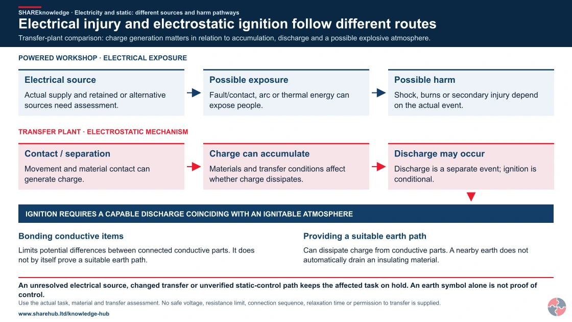
Full written explanation
Two separate conceptual pathways are shown. The workshop pathway connects an electrical source, possible contact/fault exposure and electrical or secondary injury. The plant pathway connects contact/separation or movement to possible hazardous charge accumulation and discharge; only a discharge capable of ignition coinciding with an ignitable atmosphere can lead to ignition. Bonding conductive items and providing a suitable earth path have different roles; a nearby earth does not automatically drain an insulating material. No actual wiring, bond connection sequence, resistance value or relaxation time is specified.
Transfer-plant comparison: charge generation matters in relation to accumulation, discharge and a possible explosive atmosphere.
- Identify both scenarios. Define actual electrical exposure separately from a credible electrostatic ignition scenario.
- Assess charge and materials. Consider the substance, transfer conditions, conductivity, equipment and potential for charge accumulation.
- Verify suitable controls. Competent assessment addresses release prevention, ignition control and the actual bonding/earthing arrangement where relevant.
- Review a changed transfer. A changed product, hose, container or operating condition needs review. A previous result does not clear a changed system.
When the evidence does not fit: An unresolved electrical source, changed transfer or unverified static-control path keeps the affected task on hold. An earth symbol alone is not proof of control.
Who acts: Responsible workshop/transfer supervisor and competent electrical or electrostatic/process specialists for the actual task.
Changed workplace
Powered workshop: Control the real electrical source and exposure route.
Flammable-liquid transfer: Assess release, charge behaviour, discharge and atmosphere together.
Evidence check: Use the actual task, material and transfer assessment. No safe voltage, resistance limit, connection sequence, relaxation time or permission to transfer is supplied.
Distinct electrical exposure and electrostatic charge/discharge mechanisms
Primary references: HSE: electrical injuries and separate mechanisms · HSE: flammable-liquid handling and static ignition
Open the complete HD image (new tab)Download image

Distinct electrical exposure and electrostatic charge/discharge mechanisms
Primary references: HSE: electrical injuries and separate mechanisms · HSE: flammable-liquid handling and static ignition
A field decision from start to hand-back — part 1 of 3


Read the complete visual as text
- 1. Task and setting: Crownway transfers flammable liquid into a portable vessel after a hose change.
- 2. People and prerequisites: Operator, supervisor and competent electrostatic/process lead; product, zone, hose and earth-point details are required.
- 3. Before the task: Verify release prevention, approved transfer method, compatible hose, vessel and bonding/earthing path.
A field decision from start to hand-back — part 2 of 3


Read the complete visual as text
- 1. Check during work: Confirm connection and continuity before flow; control filling and watch for leaks or alarms.
- 2. Stop, hold or refer: Missing clip, failed continuity, changed product or vapour release stops transfer.
A field decision from start to hand-back — part 3 of 3


Read the complete visual as text
- 1. Completion and hand-back: Inspect and document the restored connection and clear impairment through the permit process.
- 2. Retained evidence: DSEAR assessment, zone drawing, continuity result, transfer record and corrective action.
Crownway Fuels Ltd
Crownway Fuels Ltd stores and transfers fuels, so static electricity matters because routine filling, sampling, tanker loading, hose connection, pumps, filters and vapour spaces can create credible ignition scenarios.
Crownway's risk register separates general electrical hazards from electrostatic ignition scenarios. General entries cover switchrooms, pumps, portable equipment, chargers and contractor electrical work. DSEAR entries cover tanker loading, drum filling, sampling, fuel filters, splash filling, hose continuity, vapour release and areas where flammable atmospheres could form.
Before transfer starts, operators confirm product, hose condition, bonding connection, earthing point, valve lineup, pump status, area classification, exclusion of ignition sources and emergency stop access. The procedure states the connection sequence, when transfer may start, what abnormal signs mean, and when to stop work. Supervisors complete field checks that verify connections rather than only reviewing completed forms.
Engineering maintains an Ex equipment register, earthing inspection schedule, hose-continuity programme and defect close-out tracker. Procurement rules prevent unsuitable plastic containers, hoses or temporary equipment entering DSEAR areas. Contractors receive a bridging document that explains Crownway's electrical isolation, hot work, static-control and hazardous-area rules before they start work.
Assurance is tiered. Operators complete simple binary checks before transfer. Supervisors sample live work quality, permits and records. Senior managers and specialist auditors review DSEAR assessments, MOC records, near misses, static-control failures, emergency arrangements and whether risk reduction actions are verified as effective. Learning from incidents is fed into procedures, procurement, refresher training and management review.
Crownway changes a loading hose before transferring flammable liquid. The operator checks product and zone, connects the specified bonding path, verifies continuity and confirms vapour controls. Transfer stops if the clip, hose, earth point or release condition differs from the approved method.
A field decision from start to hand-back
Task material and setting: Crownway transfers flammable liquid into a portable vessel after a hose change.
People and prerequisites: Operator, supervisor and competent electrostatic/process lead; product, zone, hose and earth-point details are required.
Before: Verify release prevention, approved transfer method, compatible hose, vessel and bonding/earthing path.
During: Confirm connection and continuity before flow; control filling and watch for leaks or alarms.
Hold or stop: Missing clip, failed continuity, changed product or vapour release stops transfer.
Completion and hand back: Inspect and document the restored connection and clear impairment through the permit process.
Evidence: DSEAR assessment, zone drawing, continuity result, transfer record and corrective action.
How do bonding and earthing differ at a fuel-transfer interface?
Use the static-control schematic to identify the separate purposes of conductive connections. The lesson does not claim verified continuity, resistance or installation adequacy.
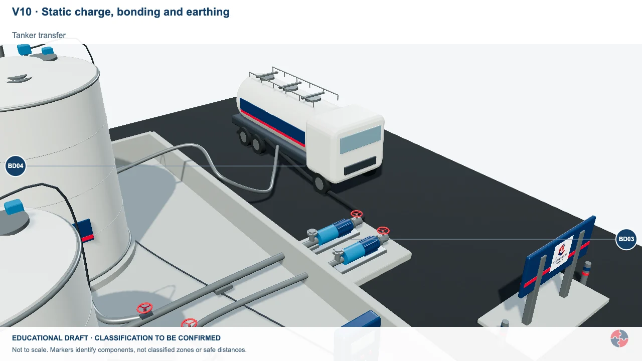
Static charge, bonding and earthing
Liquid movement can generate charge. A specified bonding or earthing arrangement controls a different part of the ignition risk.
Activity focus: Identify the intended connection and its verification evidence in the actual transfer design.
Contextual workplace scene. Use the task, control and evidence checks in this section; appearance alone does not establish safe conditions, individual health or approval.
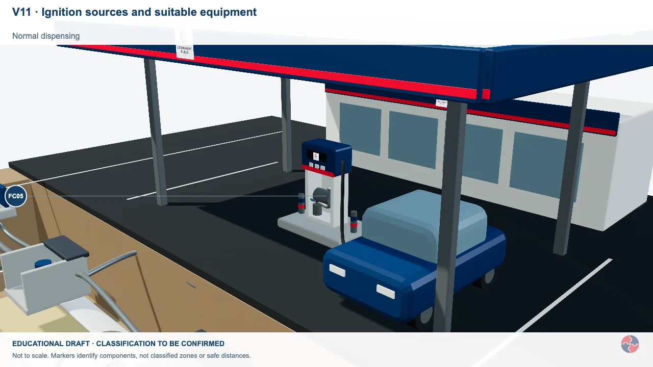
Ignition sources and suitable equipment
Electrical faults, hot work and other ignition sources matter where an explosive atmosphere could form.
Activity focus: Link equipment selection to the assessed atmosphere and actual dossier.
Contextual workplace scene. Use the task, control and evidence checks in this section; appearance alone does not establish safe conditions, individual health or approval.
Educational illustration, not to scale. Coloured zones are teaching examples, not a site-specific hazardous-area classification.
What training is needed for electricity and static electricity?
Training should be layered so general workers recognise danger and higher-risk roles can control the technical scenario.
General awareness should explain electric shock, damaged equipment, unsafe charging, static discharge, ignition sources and why defects must be reported. Short topical training is needed for workers handling flammable liquids, powders, transfer hoses, bonding clips, DSEAR areas or electrical test equipment. Supervisors and managers need deeper training on risk assessment, permit control, inspection evidence, contractor oversight and incident learning.
Technical electrical work must be carried out by competent electrical workers. Static-control competence also needs practical verification: people should be able to demonstrate the right bonding sequence, identify damaged clips, explain why plastic containers may be unsuitable and stop transfer when conditions are not right.
| Role | Learning | Demonstration | Assessor | Record | Reassess when |
|---|---|---|---|---|---|
| People near transfer areas | Recognise release, static discharge and exclusion signals | Identify a vapour or dust release and keep clear | Process supervisor | Observed induction | New process or missed signal |
| Transfer and powder operators | Check product, zone, hose and bonding path before flow | Connect, inspect and verify the specified path; stop on a failed check | Task supervisor | Observed transfer and continuity record | New product, hose or failure |
| Electrostatic and Ex specialists | Assess actual substance, charging mechanism and ignition controls | Review classification and demonstrate scoped inspection | Competent process or Ex lead | Technical assessment and authorisation | Changed substance, plant or incident |
| Transfer supervisors and permit issuers | Coordinate release controls, sequence and restart | Hold transfer after a leak or broken bond and verify recovery | Process lead | Permit and field observation | Changed transfer or repeated failure |
| Process designers and managers | Reduce release and charging through design and suitable equipment | Trace vessel, hose and zone specification to evidence | Competent process manager | Design review and action closure | New product or process trend |
| Safety advisers and auditors | Check DSEAR scope, source limits and effectiveness | Trace a failed continuity check to corrective action | Independent competent reviewer | Audit and action record | New evidence or recurring incident |
Course attendance is only one input. Observe performance on the actual task, record the scope of authorisation and reassess after change, defect or incident. First aid and electrical repair require different competence.
How does this topic support NEBOSH Diploma study?
This topic supports NEBOSH Diploma study by linking electrical injury, static ignition and evidence-based risk control.
For DN3 11.10, learners should be able to advise on electrical hazards, shock, burns, arcing, fire, explosion, static electricity, earthing, bonding, isolation, inspection, portable equipment, live work and electrical competence. Strong answers explain the difference between direct electrical injury and electrostatic ignition, then recommend controls that match the scenario.
In a case study, avoid generic answers such as 'train staff and inspect equipment'. If the scenario involves flammable liquid transfer, discuss charge generation, vapour atmosphere, container suitability, bonding, earthing, transfer rate, Ex equipment, DSEAR assessment and verification. If the scenario involves testing a panel, discuss isolation, proof dead, live-work justification, test equipment, barriers, competence and emergency arrangements.
How can management arrangements support this topic?
HSE’s Plan–Do–Check–Act guidance helps assign ownership, deliver controls, check evidence and improve weak arrangements. Apply the relevant legal duties and task-specific technical evidence separately.
Official management guidance: HSE Managing for health and safety (HSG65)
HSE’s Plan–Do–Check–Act guidance helps assign ownership, deliver controls, check evidence and improve weak arrangements. Apply the relevant legal duties and task-specific technical evidence separately.
What are the warning signs that electricity or static electricity is not controlled?
Warning signs are visible when equipment, procedures or people show that assumptions are replacing verified controls.
Weak signals should be treated seriously because electrical and static incidents can escalate quickly. A broken bonding clip, a missing earth lead, a plastic funnel used with flammable liquid, repeated RCD trips, scorch marks, taped cables or operators starting transfer before connections are checked all show that barriers may be weakening.
In DSEAR areas, the important question is not just whether a defect exists. It is whether that defect could align with a flammable atmosphere, dust cloud, poor ventilation, transfer activity or emergency weakness to create a major event.
| Warning sign | How harm can occur | Action |
|---|---|---|
| Bonding lead missing or damaged | Charge may discharge as a spark during transfer. | Stop transfer and repair/replace. |
| Plastic container used for flammable liquid | Charge may accumulate and ignite vapour. | Use suitable container and review procedure. |
| Taped electrical cable | Insulation may fail and expose live parts. | Remove equipment from use. |
| Repeated RCD trips | Fault or overload may be present. | Investigate; do not repeatedly reset. |
| No DSEAR review after process change | New static or ignition scenario may be missed. | Complete MOC and reassessment. |
| Operators cannot explain bonding sequence | Critical control may not be applied before transfer. | Retrain and verify competence. |
Chemical hazard symbols: what do they mean?
Exploding bomb
Explosive, self-reactive or organic peroxide hazards.
Flame
Flammable, self-heating or pyrophoric substances.
Flame over circle
Oxidising substances that can intensify fire.

Gas cylinder
Gas under pressure.
Corrosion
Skin burns, eye damage or corrosive to metals.
Skull and crossbones
Acute toxicity.

Exclamation mark
Irritation, harmful effects or skin sensitisation; some classifications cover drowsiness, dizziness or ozone-layer hazard. Read the actual hazard statements. Skin sensitisation differs from respiratory sensitisation.
Health hazard
Serious health hazards, including organ damage, aspiration hazard, respiratory sensitisation, cancer and reproductive effects; some can follow a single exposure.
Environment
Hazardous to the aquatic environment.
What do the acronyms and key terms mean?
Acronyms should be explained because electrical and DSEAR language can be a barrier for non-specialists.
| Term | Full expansion | Meaning here |
|---|---|---|
| ATEX | Atmosphères explosibles (explosive atmospheres) | Equipment and protective systems used in potentially explosive atmospheres. |
| Bonding | Bonding | Connecting conductive items together to reduce potential difference. |
| DSEAR | Dangerous Substances and Explosive Atmospheres Regulations | Dangerous Substances and Explosive Atmospheres Regulations. |
| EAWR | Electricity at Work Regulations | Electricity at Work Regulations. |
| Earthing | Earthing | Connecting conductive equipment to earth so charge or fault current can dissipate safely. |
| Ex equipment | Equipment for explosive atmospheres | Equipment selected for use in explosive atmospheres. |
| RCD | Residual current device | Residual Current Device. |
| Static discharge | Static discharge | Sudden movement of accumulated charge, often seen as a spark. |
| Zone | Hazardous-area zone | Hazardous area classification based on likelihood and duration of explosive atmosphere. |